


SmartVue Operator’s Manual
10-0004-R13
81
(Note: selecting
Off, shuts off the serial communications interface. Selecting
Stream sends data using SmartVue’s data streaming protocol and is described in
Section 11.0)
2.
Set the
Slave Address for the SmartVue between 1 and 247. The value should
not conflict with any other devices on the connected Modbus network.
3.
Set the
Baud Rate to the desired value. Options include: 600, 1200, 2400, 4800,
9600, 14400, 19200, 38400, 57600, and 115200 bits per second.
4.
Set the
Parity. The options are Odd, Even, or None. This should match the
configuration of the master device.
5.
Set the
Stop Bits to either 1 or 2. This should match the configuration of the
master device.
6.
Set how 32-bit wide data should be transmitted: high-order register first or low-
order register first. This can be set separately for floats and integers.
7.
The
Response Delay, if needed, can be used to set the amount of time to wait
after the SmartVue receives a command and before it sends a response. This may
be required for communications paths that have a half-duplex part like RS485.
8.
Press
OK to apply your settings.
To select a Process data register to read using Modbus
1.
Select
MENU > Communications > Modbus Regs & Diag > Process/Control
Registers.
2.
Select a vacant Process/Control register address by tapping the area in the
Data
Point column, and then press Add. Available Process/Control registers range
from 201 to 263. Use the arrow buttons to navigate the range of registers.
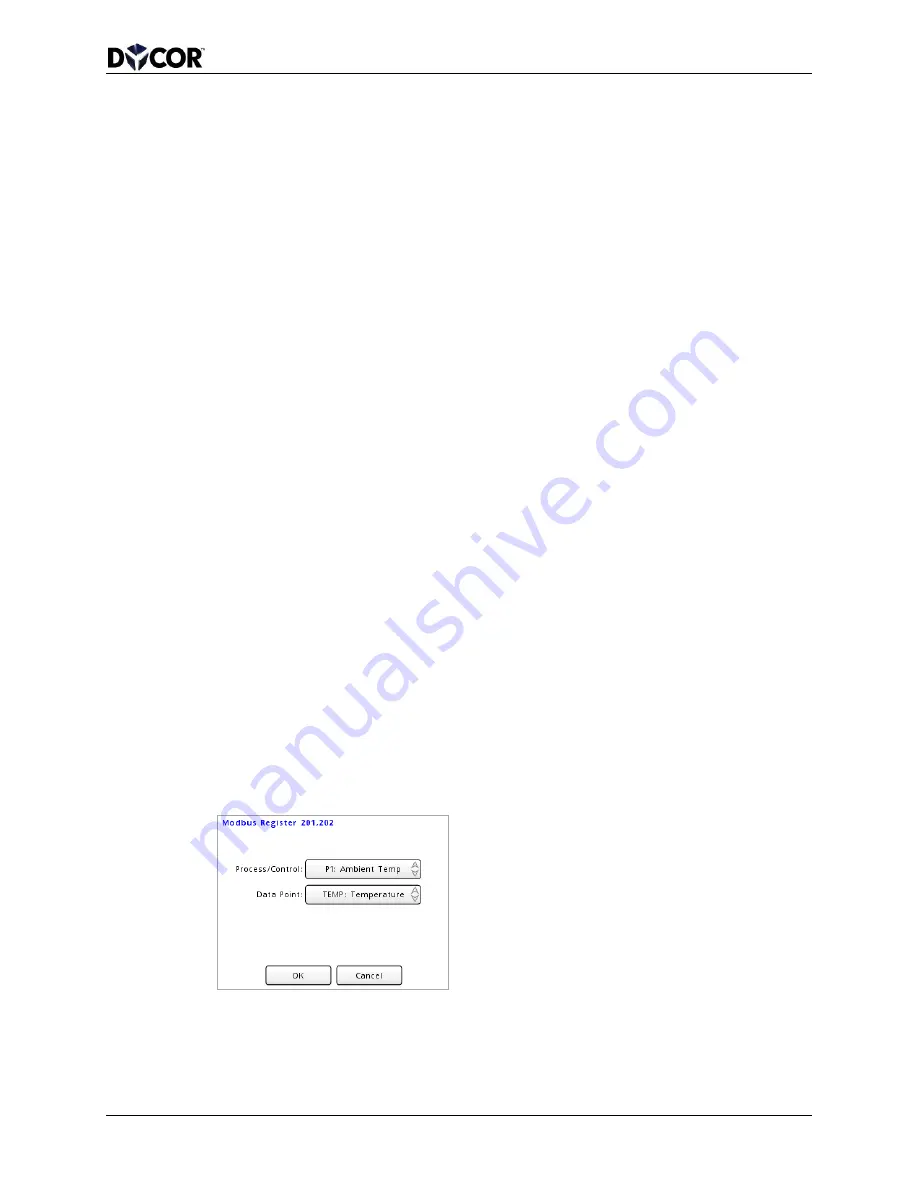
3.
On the selected Modbus Register screen, choose the Process or Control Process
that you wish to provide a data point for. (Only enabled processes will be
available). Next, choose the
Data Point, which will either be a measured value or
its status (the type of process or a potential error code).
4.
Press
OK. The selected process will be listed on the Modbus Process/Control
Registers screen. In this example, an RTD temperature sensor is connected, and
Process 1 is configured to handle the input data.


