Dycor SmartVue Process Control Monitor Operator'S Manual Download Page 103


SmartVue Operator’s Manual 

10-0004-R13


93 


5.


Press 

OK


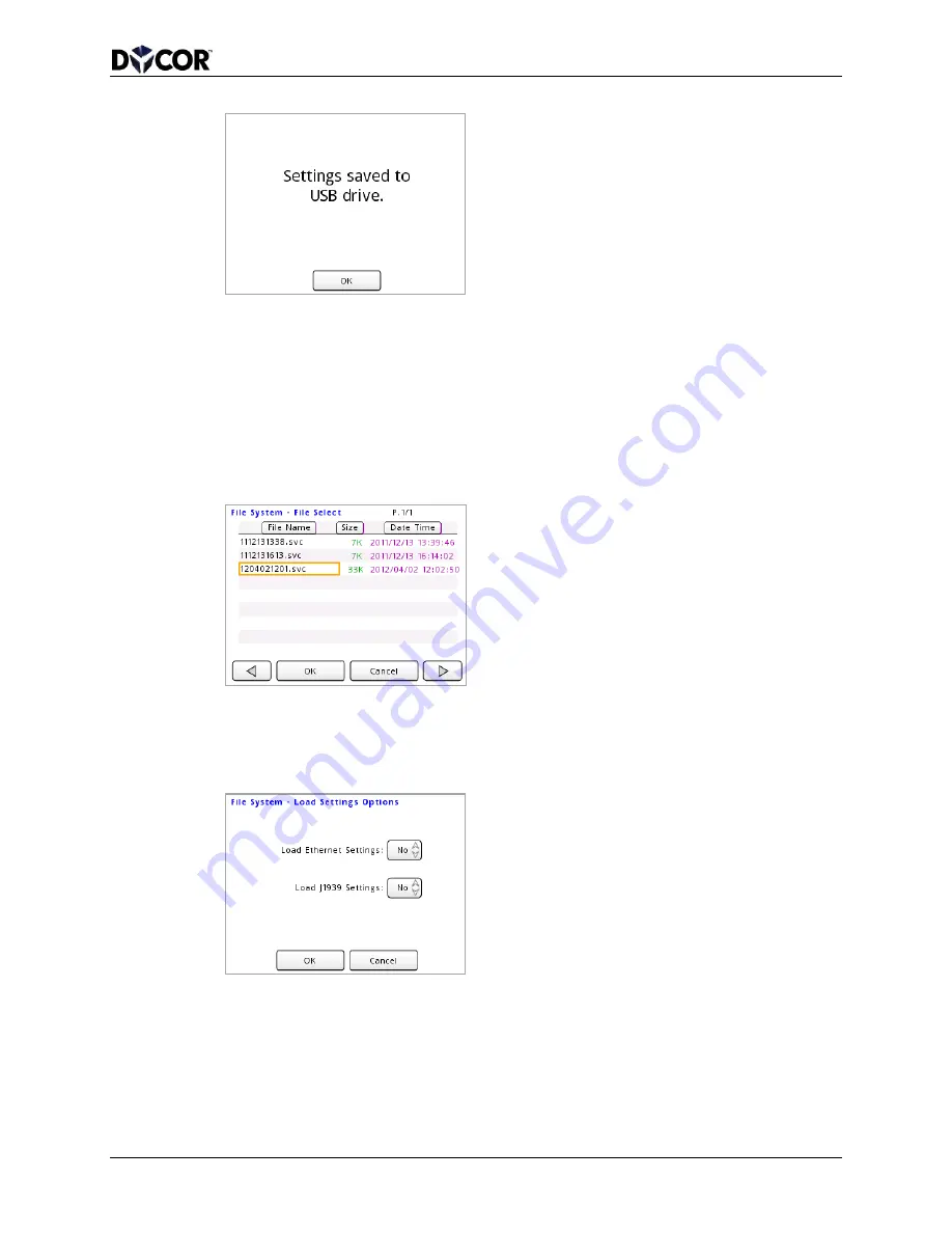
To load a SmartVue configuration file from a USB flash drive 

1.


Insert a USB flash drive into the USB port. 

2.


Select 

Main Menu > File System > Load Settings.  This will display a File 

Select screen listing all .svc files on the flash drive along with the file size and a 
Date/Timestamp.  Press a file name to select it. 


3.


Press 

OK.  When loading a configuration file, you have the option of preserving 

the current Ethernet and/or J1939 communications settings without overwriting 
them with the settings in the file.  Specify 

Yes if you wish to load the settings 

stored in the file you selected. 


4.


Press 

OK.  A warning message is displayed to remind you that the newly loaded 

processes and outputs will be disabled until they are manually run. 

Summary of Contents for SmartVue Process Control Monitor

Page 1: ...or Proprietary and Confidential Dycor Technologies Inc 4620 74 Avenue NW Edmonton Canada T6B 2K3 Telephone 780 486 0091 Fax 780 486 3535 www dycor com Process Control Monitor Operator s Manual Revision 13 ...

Page 2: ...s manual without obligation to notify any person or organization of such changes or improvements Go to www smartvue ca for current updates and supplemental information concerning the use of this product SmartVueTM is a registered trademark of Dycor Technologies Inc and may not be used without the express written permission of Dycor Contact Information Dycor Technologies Inc 4620 74 Avenue NW Edmon...

Page 3: ...NVIRONMENTAL DAMAGE DYCOR ACCEPTS NO LIABILITY FOR INCLUSION IN SUCH EQUIPMENT OR APPLICATIONS AND THEREFORE SUCH INCLUSION AND OR USE IS AT THE CUSTOMER S OWN RISK DO NOT USE THE SMARTVUE TO DIRECTLY CONTROL EQUIPMENT SUCH AS MOTORS VALVES OR ACTUATORS NOT PROPERLY EQUIPPED WITH SAFEGUARDS FOR SAFTEY PURPOSES THE EARTH GROUND TERMINAL IS ELECTRICALLY CONNECTED TO THE EXPOSED CONDUCTIVE PARTS OF T...

Page 4: ...ed the price of the individual unit which is the basis of the claim In no event shall Dycor be liable for any loss of profits loss of use of facilities or equipment or other indirect incidental or consequential damages Trademarks Products named in this document may include copyrights trademarks or registered trademarks and are acknowledged as the property of their respective companies FCC Notifica...

Page 5: ...3 Total Rate Counters 14 3 4 Temperature 15 3 5 Voltage Outputs 16 3 6 Frequency Outputs 16 3 7 4 20mA Calibration 17 3 8 Logic Thresholds 17 4 0 Setting Up a Process 18 5 0 Setting Up a Control Process 23 6 0 Assigning and Configuring a Meter 27 7 0 Setting Up an Output 32 7 1 Using the Current Loop Outputs 33 7 2 Using the Analog Voltage Outputs 35 7 3 Using the Frequency Outputs 35 7 4 Using th...

Page 6: ...s Communications 74 12 1 Reading Process Data via Ethernet TCP 76 12 2 Reading Process Data Serially 80 12 3 Reading J1939 Data 83 12 4 User Registers 84 12 5 Communications Diagnostics 85 13 0 Updating the Firmware 87 14 0 Password Protection 89 15 0 File System 91 15 1 Saving and Loading SmartVue Settings 92 16 0 Data Logging 95 16 1 Data Logging Setup and Status 96 16 2 Exporting and Deleting D...

Page 7: ... Appendix 117 21 1 Mechanical Drawings 117 21 2 Panel Mounting the SmartVue 118 21 3 Power and Signal Connections 119 21 4 Modbus Register Mapping 122 21 4 1 Discrete I O Function Code 2 Read Only bit 122 21 4 2 I O Registers Function Code 3 or 4 Read Only 123 21 4 3 Process Control Registers Function Code 3 or 4 125 21 4 4 User Registers Function Code 3 4 6 or 16 Read or Write 125 21 4 5 J1939 SP...

Page 8: ...0mA OUT 1 in passive mode 34 Figure 7 3 Voltage device connected to VOUT 1 35 Figure 7 4 Frequency input device connected to FOUT 1 35 Figure 7 5 Digital output configuration screens 36 Figure 7 6 Digital output on off behavior for Threshold mode 37 Figure 7 7 Set Outputs screens for latching mode with an analog input source 37 Figure 7 8 Pressing an enabled indicator button on the Meter screen is...

Page 9: ...e 16 2 Data Logging Settings screen 96 Figure 16 3 The Data Logging Status screen 99 Figure 17 1 Brightness configuration screen 103 Figure 17 2 Touch Screen Calibration screen 104 Figure 17 3 The Monitor Data screen 105 Figure 17 4 Date Time screen 105 Figure 17 5 The Information screen 106 Figure 19 1 The Boot Menu 108 Figure 19 2 The Flash ROM test will require that the application firmware be ...

Page 10: ...2 1 Special keyboard keys 5 Table 2 2 The Main Menu 6 Table 4 1 SmartVue Process Types 18 Table 6 1 RTD Error Messages 31 Table 10 1 Status lamps and their meanings 68 Table 12 1 DTC Modbus register mapping 84 Table 21 1 SmartVue Terminal Block Pinout 119 ...

Page 11: ...al interface that is navigated using its touch screen Settings may be permanently stored in the device s memory and it will start up with its last saved configuration The SmartVue s compact size easy to use interface and versatility make it an effective tool for control and monitoring in a variety of industrial applications The SmartVue operates around the concept of a user defined process that re...

Page 12: ...ply is needed The SmartVue requires a 10 to 30 VDC externally fused power source connected to J4 1 positive and J4 2 ground To protect the unit from potential electrostatic discharge J4 3 EARTH should be connected to the metal surface of the mounting enclosure 1 2 3 4 5 6 Figure 2 1 External power connection The power connections are also listed in Table 21 1 ...

Page 13: ... The Boot Menu displays options for running memory diagnostics configuring the LCD brightness calibrating the touch screen and updating the firmware version Once the unit s self test is completed the Meter screen will be displayed A few examples of the Meter screen are shown in the figure below Figure 2 3 The Meter screen The Meter screen displays up to four meters so that the input data you provi...

Page 14: ...erical entry are all achieved by touching or pressing the related graphic representation When a textbox designed for character entry is pressed a keyboard will be displayed Figure 2 4 Likewise when a textbox meant for numerical entry is pressed a numerical keypad either decimal or hexadecimal is displayed Figure 2 5 Figure 2 4 The various keyboards for text symbol entry Figure 2 5 Decimal and hexa...

Page 15: ...l 10 0004 R13 5 Table 2 1 Special keyboard keys Backspace Toggle between upper and lower case Displays a combined numeric and symbol keyboard Display a symbols only keyboard Enter the value into the selected text numeric field ...

Page 16: ...ed and or disabled processes that you can configure to use a SmartVue input Communications Displays a menu that allows various communications protocols to be configured including Ethernet and J1939 11 Control Processes Displays a menu of currently assigned and or disabled control processes that you can configure to use a SmartVue input SmartVue Provides access to the password protection system dis...

Page 17: ...creen when one or more history graphs is being displayed since the buffered history data must be read to render the graphs A small lock icon is displayed next to each block for a screen that can be locked and thus made inaccessible when password protection in turned on Refer to Section 14 0 Password Protection for more information ...

Page 18: ... Out 1 2 DIN VIN DOUT 1 6 Set Outputs 2 Monitor Data Information Upload Firmware Login Logout Password Brightness Calibrate Touchscreen Meter Screen Date Time File System Ethernet Settings J1939 Menu Configuration SPN List User Device List Diagnostics Config Active Device List SPN Data Monitor PGN Request List Diagnostics Display Load Settings from USB Save Settings Run Stop Services Data Streamin...

Page 19: ...lished and local touch screen control has been disabled The main password has been set and the user is logged in The main password has been set and the user is logged out preventing access to certain configuration screens One or more active DTCs has been detected on the J1939 bus A process configuration change has affected one or more associated outputs disabling it it must be reviewed and manuall...

Page 20: ...option of using the Load Defaults from IOConfig button to load default values setup in the Configure I O options described below Figure 3 1 The Configure I O menu Remember to save your settings If the power is shut off to the SmartVue any changes you make to the configuration will be lost unless you save your settings first A small diskette icon will appear in the upper right of the screen to remi...

Page 21: ...epresent the expected range of current values that the SmartVue may receive from a sensor or some other device For an output the values on the right represent the expected range of currents that the unit will provide to an external device In either case current values may exceed the given range since the values are merely used to calculate corresponding scaled values Example Connect a loop powered...

Page 22: ...tion as a digital input digital output or analog voltage input designed for an input range of 0 to 10 volts When you navigate to the Multipurpose I O configuration menu shown below the buttons indicate the currently configured I O type for each channel in parentheses An assortment of I O types is preset on the SmartVue Figure 3 5 The Multipurpose I O configuration menu ...

Page 23: ...yed on the meter screen for a low digital input signal High State Digital Input The characters that will be displayed on the meter screen for a high digital input signal HiZ State Digital Output The characters that will be displayed on the meter screen when the output is in a high impedance state Pull up Turns the pull up resistor on or off for the given digital input or output Voltage Input Label...

Page 24: ...ation menu is shown in Figure 3 6 Figure 3 6 The Total Rate Counters configuration menu The Total Rate Counters configuration settings are summarized as follows K Factor A scaling value by which the count value is divided to convert the input pulses to engineering units Label The identifying label that will appear on the meter screen Units The engineering units the value will be displayed with Tim...

Page 25: ...ocess that uses them Figure 3 7 The Configure I O Temperature screen The temperature configuration settings are summarized as follows Label The identifying label that will appear on the meter screen Units The temperature scale and units the value will be displayed with C F K for Kelvin Resistance This should correspond to the resistance specification of the RTD being used The SmartVue supports 100...

Page 26: ...0 bar pressure is equal to a 1 00 volt output on 0 10V OUT 1 while 20 00 bar equates to an output of 10 volts Figure 3 8 The Configure I O 0 10V OUT 1 screen 3 6 Frequency Outputs Like the voltage outputs the frequency outputs can be configured with desired labels units and scales to work in conjunction with a process that provides a square wave output to a device The screen below shows a possible...

Page 27: ... you wish to calibrate 4 20mA IN 1 or 2 and then press the Calibrate 4mA button to set the measured raw current value as the calibrated reference for 4 mA 3 Likewise set the supply to deliver 20 mA and then press the Calibrate 20mA button to set the raw value as the calibrated reference for 20 mA 4 Press OK 3 8 Logic Thresholds The logic thresholds define the voltage levels at which a low state wi...

Page 28: ...the SmartVue s functional components for a basic process The dashed blocks indicate an optional setup for a process Figure 4 1 A basic process The SmartVue allows up to eight processes and two control processes to be configured The types of processes that can be configured are summarized in Table 4 1 Table 4 1 SmartVue Process Types Process Type Input Modes Total Rate Counter 1 Counter or Quad x2 ...

Page 29: ...oint channel that will supply the measured value Label units other settings Enter a label and engineering units that will appear on the Meter Screen To quickly load previously defined values are not what you want to use press the Load Settings from IOConfig 3 Press the left or right arrow button to advance to the next configuration screen for the process Note the selected input type will determine...

Page 30: ...ntrol process will have its internal error flag set A meter configured for this process will display TIMEOUT 3 Keep last value After the timeout the process or control process will continue to use the value in the register 4 Keep last error Same as above but also the process or control process will have its internal error flag set A meter configured for this process will display TIMEOUT During the...

Page 31: ... a Temperature Process Using an RTD Resistance Temperature Detector 1 Connect a 100 ohm or 500 ohm RTD 3 wire to the J2 terminal connector as shown in Figure 4 2 The temperature sensor may of course be connected to the end of a long cable so that it can be placed in a location where you wish to make an accurate temperature measurement Figure 4 2 J2 wiring for an RTD 2 Select MENU Processes to disp...

Page 32: ...ve your temperature measurements right away you will likely want to display this information on the Meter Screen The example in Section 6 0 Assigning and Configuring a Meter will show you how to do just that Notes The RTD value displayed on the Monitor Data screen will be with the units configured using the Configure I O Temperature screen and is not affected by the process configuration If a faul...

Page 33: ...losed loop control process In addition to the modified variable various other parameters for a control process can be assigned to a meter so it can be displayed on the Meter screen including the feedback variable the error value and the setpoint value The control process input value can of course also be chosen for display You also have the choice of using either a manually entered setpoint or an ...

Page 34: ...oint value PID Ext SP Closed loop PID control that uses another input as the setpoint PID Ext SP w MULT Closed loop PID control that uses another input as the setpoint and an entered value to multiply the setpoint input Disabled The Control Process and its associated output are disabled Type Select the type of input that will serve as the sensor feedback signal Input Select the input channel for t...

Page 35: ...alues for the Setpoint PID mode only the PID coefficients Kp Ki and Kd as well as Imax Imin and the Sample Interval Kp Ki and Kd are the PID algorithm coefficients or gains Imax and Imin set limits for the I term preventing it from becoming too large and are specified in engineering units for the process output The values you choose depend on the capability of the system being controlled The valid...

Page 36: ... Rate inputs is acquired every 100 ms The setpoint units will be display in red on the PID Parameters screen if they do not match the feedback units The closed loop error value is computed by determining the difference between these two values When you assign a control process s modified variable to a Modbus process control register then the control will be allowed to run since an output has been ...

Page 37: ...te of a digital output If you want to control a digital output based on the value of a certain input you can set the same or different values using the Set Outputs configuration for a digital output Refer to Section 7 0 Setting Up an Output The history graph will display a red vertical line if there is an error reading an incoming data value This can occur just after the unit has been powered up a...

Page 38: ...Press an arrow button again to return to the Meters menu screen 3 Press the button for the meter position you wish to configure This will display the meter configuration screen Depending on the selected meter type you will see a slightly different screen 4 Configure the meter Meter Type Choose from Digital History Graph or Off Process Control Selects the enabled process you wish to display Data Po...

Page 39: ...n which one you want to configure You can turn on one or both indicators and specify thresholds for each Some example screens are shown below 2 Choose the Signal Source Threshold values Meter and indicator labels and colors Signal Source lets you choose the source that will control the indicator s on off state Possibilities include the meter value a digital input or a digital output Note other tha...

Page 40: ...ntended changes for critical applications 3 Press Exit This will return you to the Meters menu 4 Press OK To configure the plot settings for a History Graph meter 1 Enter the meter s configuration screen and press an arrow button to navigate to the Plot Settings screen Color The line data color there are nine to choose from Plot Type Choose from Thin Thick or Fill Y Axis Max Y Axis Min Specifies t...

Page 41: ...asurement is above the measurement range of the sensor UNDER The temperature measurement is below the measurement range of the sensor 1 Select Meters from the Main menu 2 Press the button for a meter position where you want the temperature process data to be displayed If desired use an arrow button to change the number of meters that can be displayed and then go back to the previous Meters menu 3 ...

Page 42: ...elected process input To setup an output to use with a Process or Control Process 1 Select MENU Set Outputs This will display the first page for the various outputs that the SmartVue provides Pressing an arrow button here will display the second page showing the multipurpose I O points Those that have been configured as digital outputs can be used 2 Press the button for the output you wish to use ...

Page 43: ...ent Loop Outputs The SmartVue s two 4 20 mA current loop outputs are each designed to work in one of two modes active where the SmartVue provides the loop power or passive where the SmartVue must rely on loop power supplied by an external device To use a current loop output as an active source it must have external excitation from a supply voltage The Field Supply is conveniently located on the sa...

Page 44: ...UT 2 4 20mA OUT 2 4 20mA IN 1 4 20mA IN 1 4 20mA IN 2 4 20mA IN 2 CL Device Figure 7 1 J1 wiring to use 4 20mA OUT 1 in active mode 1 2 3 4 5 6 7 8 9 10 11 12 Figure 7 2 J1 wiring to use 4 20mA OUT 1 in passive mode Notes The field supply voltage outputs and current loop inputs and outputs are isolated from all other connections ...

Page 45: ...is the 24V terminal of the field supply Figure 7 3 shows the wiring for connecting a voltage device to VOUT 1 1 2 3 4 5 6 7 8 9 10 11 12 Figure 7 3 Voltage device connected to VOUT 1 7 3 Using the Frequency Outputs The two frequency outputs each provide a square wave from 0 to 6 250 Hz Figure 7 4 shows how a device requiring a frequency input would connect to the SmartVue 13 14 15 16 17 18 19 20 2...

Page 46: ...e connected to it will conduct a current and thus be turned on If needed internal pull up resistors can be enabled to provide a pull up of 10 to 30 volts through an internal reference diode This is accomplished through the Configure I O Multipurpose I O setup screen 7 4 1 Threshold Mode Figure 7 5 shows the configuration screens for a digital output for which the state depends on an analog input i...

Page 47: ...until it is manually reset to its previous state Figure 7 7 Set Outputs screens for latching mode with an analog input source Two latching conditions are possible greater than or equal to a value or less than or equal to a value If the latch condition is met the latch output can be configured to toggle low or to the high impedance state HiZ A latch can be cleared by pressing OK on the Set Outputs ...

Page 48: ... the digital source is either high or low Figure 7 9 Set Outputs screen for latching mode with a digital input source Figure 7 9 shows that output DOUT 6 will be latched to HiZ when the digital input signal named T1 is high 7 4 3 Switching Mode The Switching mode toggles a digital output depending on the state of the selected digital input Polarity of the output can be configured to be either Norm...

Page 49: ...or some external device To set an output to a fixed value 1 Select MENU Set Outputs 2 Press the button for an output that you wish to set to a fixed value 3 Turn on the output by selecting Yes using the Enabled spinner 4 Set the Process Control spinner to Fixed You will see a screen like either of the ones below depending on the type of output you selected 5 Enter a fixed value for the output For ...

Page 50: ... I O Type to Voltage Input Also set an appropriate scale default You can alter this scale later if you choose to override these defaults I O configuration is discussed in more detail in Section 3 0 2 Using a sensor that provides 4 20 mA and an appropriately sized potentiometer hookup the J1 and J2 connectors as shown in Figure 7 12 Figure 7 12 J1 and J2 wiring to use 4 20mA OUT 1 as external setpo...

Page 51: ...7 4 with an appropriate voltage level You should end up with a screen like the one below and then press OK 7 Setup a meter to display the current loop input for the sensor You can also setup additional meters to display other values for the control process such as the error following the instructions in Section 6 0 8 Save your settings if you want to preserve this setup MENU File System Save Setti...

Page 52: ...zero volts current loop outputs are set to the minimum value digital outputs are set to high impedance and frequency outputs are set to zero hertz The Meter screen will display inputs values as with the Run mode Stop Process Control disables the processes and no further input values are displayed on the Meter screen Outputs are shut off as with the Run with Outputs Off mode described above Figure ...

Page 53: ...SmartVue Operator s Manual 10 0004 R13 43 Figure 8 3 The Meter screen when the Disabled Configuration mode is engaged ...

Page 54: ... unique host part When sending data to a device with a different network part it must be sent through a router to reach its destination i e to a different network If they are the same no router is needed The host part sets how many unique IP address are allowed on the network So with a subnet mask of 255 255 255 0 the first three parts of the IP address will form the fixed network number while the...

Page 55: ...ddress for the network node router that connects your network to an outside network Typically it shares the first three values of the IP address and uses 1 for the last value 4 Press OK The Services button provides access to the various configurable features that are available for Ethernet communications Figure 9 2 Ethernet Services Menu Note settings for the following Ethernet services are descri...

Page 56: ... for controlling how and what data will be streamed 2 Set Data Streaming to On Figure 9 3 Ethernet Settings Data screen 3 Enter the data port number The software you use to send commands to the SmartVue must use this port The default port number is 2641 4 The Command Checksum setting is set to Off by default set it to On to include a checksum value at the end of each data line The Off setting will...

Page 57: ... added using the J1939 Diagnostics Configuration screen Press the J1939 DTCs button to display them and then select the ones you want to receive streamed data for by pressing the device name If the list is blank no ECUs have yet been selected through the J1939 Diagnostics Configuration Refer to Section 10 7 for more information regarding DTCs Press OK to accept your changes and then OK again to re...

Page 58: ...are used Bold is used for commands and options Italic is used to show generic options that should be replaced with user supplied values surround optional elements The brackets themselves are not entered CS indicates the 16 bit hexadecimal checksum value in the range 0000 to FFFF CRLF represents the carriage return and line feed characters Note that all connections to a SmartVue share the same inte...

Page 59: ...n can be 1 to 16 Examples Obtain the data set for Process 2 followed by Process 1 C000 P2 P1 CS CRLF If the command is successful an OK response will be received and then the periodic data transmission will begin starting with the characters D000 OK R000 CS CRLF D000 SV009S000000 2011 06 30 15 51 00 P2 data LENGTH CS CRLF D000 SV009S000000 2011 06 30 15 51 01 P2 data LENGTH CS CRLF Whenever a data...

Page 60: ...e that 01D5 is the calculated checksum for this response 9 3 3 Poll Data 002 C002 d1 d2 dn CS CRLF The Poll Data command works the same way as the Stream Data Start command but only one data packet is returned and it is included in the command response packet Examples Obtain one complete data set C002 P1 P2 P3 P4 C1 C2 IO CS CRLF If the command is successful an OK response will be transmitted with...

Page 61: ...owing error codes may be encountered BUF indicates a command buffer overflow CMD means that an invalid command was received CSM indicates a checksum error In this case the command was likely corrupted in transmission and should be resent DUP indicates a duplicate parameter was received The sent command will also be returned with this error PAR means an invalid parameter was received The sent comma...

Page 62: ...MENU Communications Ethernet Settings and set the Checksum to Off 3 Run the PuTTY program on your PC 4 Enter the IP address Port number and a Connection type of Telnet as shown in the program window below You can also give the session a name i e SmartVue and save it for easy retrieval later 5 Select your newly saved session and then click Open or simply double click its name to connect and begin t...

Page 63: ...IC Input Channel 1 7 Integer SPDATA1 Scaled Process Data 1 Rate Float User specified SPDATA2 Scaled Process Data 2 Total Float User specified 1 7 PT Process Type 1 Standard 1 IT Input Type 7 SPN Analog 7 IC Input Channel 1 32 Integer SPDATA1 Scaled SPN Data Float User specified 1 8 PT Process Type 1 Standard 1 IT Input Type 8 SPN State 8 IC Input Channel 1 32 Integer SPDATA1 Raw State Data in deci...

Page 64: ...tpoint Float User specified RES Reserved Float ITERM I Term Float User specified DTERM D Term Float User specified 3 CT Control Type 3 PID External SP w Multiplier 3 FBIT Feedback Input Type 1 2 5 or 6 Integer FBIC Feedback Input Channel 1 6 Integer SPIT Setpoint Input Type 1 2 5 or 6 Integer SPIC Setpoint Input Channel 1 6 Integer MV Modified Variable Float User specified FB Feedback Float User s...

Page 65: ...er DI5 Digital In 5 Integer DI6 Digital In 6 Integer CLO1 Current Loop Out 1 Float mA CLO2 Current Loop Out 2 Float mA VO1 Voltage Out 1 Float V VO2 Voltage Out 2 Float V FO1 Frequency Out 1 Float Hz FO2 Frequency Out 2 Float Hz DO1 Digital Out 1 Integer DO2 Digital Out 2 Integer DO3 Digital Out 3 Integer DO4 Digital Out 4 Integer DO5 Digital Out 5 Integer DO6 Digital Out 6 Integer STEMP Scaled Te...

Page 66: ...2 3 4 5 6 7 Current Loop Input 1 4 20mA IN 1 4 20mA IN 2 Voltage Input 2 VIN 1 VIN 2 VIN 3 VIN 4 VIN 5 VIN 6 Digital Input 3 DIO 1 DIO 2 DIO 3 DIO 4 DIO 5 DIO 6 Reserved 4 Temperature Input 5 RTD Total Rate Input 6 TACH IN 1 TACH IN 2 CTR1 CTR2 CTR3 QENC1 QENC2 Temperature Sensor Status TEMPSS Description 0 No Error 1 RTD Connection Error 2 Reading Under 3 Reading Over J1939 SPN Data Field Label F...

Page 67: ...Data M1 M5 M1 unsigned 16 bit integers group M2 signed 16 bit integers group M3 unsigned 32 bit integers group M4 signed 32 bit integers group M5 32 bit floats group MBxxx 1st Modbus register in the group integer or float xxx 401 409 417 433 or 449 MBxxx 8th Modbus register in the group integer or float xxx 408 416 431 447 or 463 Example A simple data packet including a single Temperature process ...

Page 68: ...Nbus 1 2 3 4 5 6 Messages transmitted on the J1939 network include values that identify data being requested or sent by ECUs Among other things each message contains a Parameter Group Number PGN source address and priority If the message is intended to be peer to peer it will also include a target address that has made the request for the information Parameters that have common characteristics are...

Page 69: ...r communications Figure 10 2 J1939 Configuration with an address type of Arbitrary Figure 10 3 J1939 Configuration with an address type of Fixed Mode Monitor Only This mode option permits the monitoring of active PGN data on the J1939 bus The SmartVue will not send any requests for additional PGNs The CANbus interface will be deactivated in this mode Send Receive With this setting the SmartVue wil...

Page 70: ...de is set to Send Receive If you wish to obtain particular SPN data that is not actively on the bus then the SmartVue must claim and address and identify itself on the bus to make the request for a PGN that includes the desired data Address Type Arbitrary Should a conflict occur when a claim is made for the Default Address see below an attempt will be made to claim another Fixed J1939 11 only A Sm...

Page 71: ...0 2 Active Device List What information is available on the bus or can be requested to be on the bus depends on which devices ECUs are connected and active on the network To see the list of active devices on the network select MENU Communications J1939 Menu Active Device List Figure 10 4 The J1939 Active Device List The Active Device List shows the list of devices that are communicating on the CAN...

Page 72: ...the J1939 Menu 2 Choose a row that has nothing entered in it by selecting the area in the Label column Notice that the selectable areas on this screen have a light grey background color 3 Press the Add button 4 Press the Search button to search for and select the desired SPN You can conveniently select from a list of active PGNs or SPNs In the example figures below the SPN button was pressed and t...

Page 73: ...n enter the address Likewise if you have a user defined device you can select an addressing mode of Arbitrary By Name and then press the Device List button to select it 7 Enter an appropriate label in the Label box to that will descriptively identify the parameter on the SPN Data Monitor screen 8 Press OK The SPN List now shows the newly added SPN You can edit an existing SPN by selecting its labe...

Page 74: ...econd window could be missed because of their short duration and the inherent nature of the discrete sampling 10 4 1 Display SPN data on the Meter Screen You can also display SPN data values on the SmartVue s Meter screen in the same way that I O data is displayed When setting up a process simply select a process type of J1939 SPN the Input spinner control will list the active SPNs that are includ...

Page 75: ...evice to the User Device List 1 Select User Device List from the J1939 Menu 2 Choose a row that has nothing entered in it by selecting the area in the Device Name column Notice that the selectable areas on this screen have a light grey background color 3 Press the Add button 4 Enter an appropriate name for the device Configure the various fields 5 Press OK The newly added device will appear on the...

Page 76: ... Search screen and then search by PGN or SPN to obtain the PGN you need 5 Select a device to choose the ECU you want to begin transmitting the data for the PGN you selected If you know the address of the device ECU that is supplying the data for the selected SPN you could specify an addressing mode of Fixed By Address and then enter the address or use the Active List button to choose it Likewise i...

Page 77: ... the bus 1 Select Diagnostics Config from the J1939 Menu 2 Choose a row that has nothing entered in it by selecting the area in the Device ECU column Notice that the selectable areas on this screen have a light grey background color 3 Press the Add button 4 Choose the device you wish to monitor for DTCs You can choose a device by using the Fixed By Address addressing mode In this case enter an ECU...

Page 78: ... The Active DTC Monitor screen On the lower portion of the screen you can page though each DTC for the selected ECU by using the arrow buttons The lower lamps will indicate the severity for the single DTC only In this case different DTC may illuminate the lamps differently You can cycle through the list of selected devices using the arrow buttons to examine the combined lamp states Table 10 1 Stat...

Page 79: ...process data IO data and J1939 SPN and DTC data The data output is organized with the same format as Ethernet data communications described in section 9 4 MB Master Slave ASCII Used for Modbus serial communications Modbus ASCII uses ASCII characters to represent the data and uses LRC error checking More bytes are needed to transmit message content than with MB RTU MB Master Slave RTU Used for Modb...

Page 80: ... application An example application is discussed in a later section Refer to section 9 3 for the command syntax Likewise for testing purposes the command checksum can be disabled For example if you want to conveniently obtain data or to test a connection via a Telnet session without having to calculate the checksum you can disable the checksum requirement To configure the SmartVue to stream proces...

Page 81: ... the Item column for the data sets you wish to receive Press Select All to check all the boxes at once or Deselect All to uncheck all of them Note remember to save the SmartVue s settings if you want your selection to persist after it has been powered off Also optionally if the J1939 communications stack is enabled then active Diagnostic Troubleshoot Codes DTCs can also be streamed for devices ECU...

Page 82: ...Vue serially The two screens below show how PuTTY is configured to communicate over comport 4 called COM4 at 9600 baud with no parity Note that the SmartVue uses 8 data bits and no flow control by default so the PuTTY configuration should also reflect this Figure 11 4 Serial communications using PuTTY Save the configured session and click Open to observe the streaming data This figure below shows ...

Page 83: ...SmartVue Operator s Manual 10 0004 R13 73 Figure 11 5 Sample serial data using PuTTY ...

Page 84: ...se Modbus registers are named Input Holding Coil and Discrete These are old PLC concepts used in the Modbus commands SmartVue has data registers that are accessible using these Modbus registers specified in the commands For example the same SmartVue Process Registers can be read by a Master sending a read input register or read holding register command Figure 12 1 Example setup showing the many wa...

Page 85: ...e process along with possible error codes the J1939 SPN and DTC data and statuses at their fixed register locations as well as a set of writable Modbus user registers There are different ways to address the registers Offset Register and Modicon The SmartVue config screens use the Register column in the tables What you can NOT do with this Modbus implementation Modbus UDP is not supported only Modb...

Page 86: ...e the SmartVue as a Modbus slave for TCP communications 1 Select MENU Communications Ethernet Settings 2 Enable the Ethernet feature and configure the network settings as per Section 9 1 3 Press the Services button and then the Modbus TCP Slave button 4 Set the Enabled option to Yes This will display the screen shown below Figure 12 3 Modbus TCP slave configuration settings ...

Page 87: ...to no activity If a master drops a TCP connection the SmartVue may not be notified so a timer is used to detect if the master is no longer connected Since the SmartVue only has three possible slave connections it important to keep this time short You can see the current connections in the Comm Diagnostics area under the Communications Modbus Regs Diag menu 9 Press OK to apply your settings The Sma...

Page 88: ...rs Cmd Delay ms Command Delay This specifies the delay between commands After receiving a response there will be a delay of at least this amount before the next command is sent This may be required for communications paths that have a half duplex part like RS485 Cycle Delay ms This is how long the SmartVue will wait after receiving the response from the last command in the polling table before sta...

Page 89: ...ge between the read and write functions the To and From labels swap on the following two register fields From To Slave Register the starting register on the slave device to read from write to In the polling table screen this is indicated in the SL Reg column The Dir column indicates the direction data is moving a read function from the slave to the SmartVue pointing right or a write function from ...

Page 90: ...g the Edit button Use the Delete button to remove a Modbus TCP connection 12 2 Reading Process Data Serially To configure the SmartVue as a Modbus slave for serial communications 1 Select MENU Communications Serial Settings RS232 Settings Select RS485 Settings if you wish to use the RS485 interface Set the Serial Mode control to one of MB Slave ASCII MB Slave RTU MB Master ASCII or MB Master RTU d...

Page 91: ...be used to set the amount of time to wait after the SmartVue receives a command and before it sends a response This may be required for communications paths that have a half duplex part like RS485 8 Press OK to apply your settings To select a Process data register to read using Modbus 1 Select MENU Communications Modbus Regs Diag Process Control Registers 2 Select a vacant Process Control register...

Page 92: ...SmartVue Operator s Manual 82 10 0004 R13 5 Press OK to apply your changes In this case the 32 bit floating point temperature data is now available for reading via Modbus from register 201 ...

Page 93: ...31006 41006 SPNDATA2 Data 1007 1008 31008 41008 SPNSTATUS3 Status The status of each SPN data register is also available with the first SPN status register being 1002 the second 1005 and so on The following table summarizes the meaning of each bit position if set Bit Position Description 0 No Data 1 Timeout 2 Over Range 3 Under Range 4 Stack Not Running 5 Data is Integer 6 Disabled Register ID 100...

Page 94: ...MP1 1103 1104 31104 41104 NCODES1 DTC1 1104 1105 31105 41105 DTC1 1_H 1105 1106 31106 41106 DTC1 1_L 1106 1107 31107 41107 FMI1 1 1107 1108 31108 41108 OC1 1 DTC2 1108 1109 31109 41109 DTC1 2_H 1109 1110 31110 41110 DTC1 2_L 1110 1111 31111 41111 FMI1 2 1111 1112 31112 41112 OC1 2 12 4 User Registers The SmartVue has a set of Modbus registers that can be written to during Modbus communication call...

Page 95: ...rom the last command that resulted in an error Here are the possible error codes Error code Meaning 1 Modbus exception code 1 returned by slave Slave does not support function code 2 Modbus exception code 2 returned by slave Slave does not support address specified in the command 3 Modbus exception code 3 returned by slave Slave does not support data value it received 4 to 11 Other uncommon Modbus...

Page 96: ...that the SmartVue does not support 2 Modbus exception code 2 was returned by SmartVue Master specified an address that the SmartVue does not support Trying to write to a read only address also causes this exception 3 Modbus exception code 3 was returned by SmartVue Master sent a bad values in the register count or data length fields 28 Received a command but has a bad CRC ErrCnt This is a count of...

Page 97: ...ication file ending with a sva extension Updating does not affect stored configuration settings To upload a new firmware version 1 Press Menu SmartVue Upload Firmware This will display the message shown in the figure below 2 Copy the SmartVue application file to a USB flash drive and insert it into the USB port on the back of the unit then press OK Pressing Cancel will return you to the SmartVue m...

Page 98: ...n Powering On If the unit if off you can press and hold on the touch screen while the unit is powered on If a USB flash drive is not detected the touch screen calibration feature will start followed by the brightness adjustment screen for the LCD you will then be prompted to insert a USB flash drive containing a file for the new firmware if you wish to update the firmware to a new version If the U...

Page 99: ... logged out The following menu items are locked when password protection is turned on and a user is not logged in Main Menu o Processes Locked process user selectable o Control Processes Locked control processes user selectable o Configure I O o Set Outputs o Communications o File System Load Default Settings o SmartVue Password To turn on password protection 1 Select MENU SmartVue Password 2 Ente...

Page 100: ...e already logged in 2 Enter the password Press the button again to log out Notes When you turn on password protection don t forget to use the Save Settings feature to save the password and on off setting otherwise if the unit is shut off it will not be password protected when you turn it back on What if I forget my password If you forget your password and you become locked out you will have to upl...

Page 101: ...ng off the SmartVue Load Settings from USB allows you to load a settings file from a USB flash drive Once loaded you must press Save Settings to keep the new settings Press Save Settings to preserve the newly loaded settings before powering off the SmartVue Save Settings to USB lets you save the SmartVue s current settings to a file on a USB flash drive File names are assigned a default value cons...

Page 102: ...g them since any connected devices circuits or sensors could also be affected leading to undesirable and possible detrimental consequences 15 1 Saving and Loading SmartVue Settings To save the SmartVue s configuration to a USB flash drive 1 Insert a USB flash drive into the USB port 2 Select Main Menu File System Save Settings 3 Use the File Name text control to specify a name for the configuratio...

Page 103: ...ong with the file size and a Date Timestamp Press a file name to select it 3 Press OK When loading a configuration file you have the option of preserving the current Ethernet and or J1939 communications settings without overwriting them with the settings in the file Specify Yes if you wish to load the settings stored in the file you selected 4 Press OK A warning message is displayed to remind you ...

Page 104: ...e been turned off In addition each meter on the Meter screen will indicate this by displaying the message DISABLED Once you are satisfied that the unit is physically connected and configured in a fashion that is suitable for your application you can run the configured processes and engage the outputs by selecting Run on the Run Stop screen which is accessed from the Main Menu ...

Page 105: ... USB flash drive Data Logging Status displays a screen that reports information about log file memory usage Pause Resume Data Logging lets you pause or resume data logging activity Export DTC Data Logs allows you to copy one or more DTC data logs to a USB flash drive DTC Data Logging Status displays a screen that reports information about DTC log file memory usage Data logging and power loss If po...

Page 106: ...efixed with a timestamp value corresponding to its creation date and time with the format YYYYMMDDhhmm xxx If set to Name you can supply your own custom prefix up to 12 characters in length A three digit numerical index will follow the name to differentiate between separately generated files DTC data logs will include a D in the index part of the file name Press Select Items to Log Select any of t...

Page 107: ...nt data file If No is selected data logging will cease when the storage capacity is reached Overwrite DTC Data If Yes is specified then when the internal storage capacity has been reached during logging older files will be overwritten with new data for the current DTC data file If No is selected data logging will cease when the storage capacity is reached Advanced The Advanced Settings screen allo...

Page 108: ...o a USB flash drive before making changes to the Advanced Settings Notes Data log files are automatically appended with a csv extension designating it as a comma separated values file csv files can be directly opened by text editors and spreadsheet programs such as Microsoft Excel For time stamped file names you will only see the numerical index increment from 000 if a new data log file is generat...

Page 109: ...to a USB flash drive 1 Select MENU File System Data Logging Export Data Logs Select Export DTC Data Logs to copy DTC data to a USB flash drive 2 In the File Name column select the data logs you wish to export Selected files will be highlighted green Additional log files may be listed on additional pages All of the data logs can be quickly selected by pressing Select All 3 Press Export A warning sc...

Page 110: ... Process Control Process and I O data from a selected log file This is helpful when you have a large log file and want to save time exporting only the relevant data you need from a desired time range To export a subset of data from a log file 1 Select MENU File System Data Logging Export Data Logs 2 In the File Name column select a single data log file you wish to export a subset from 3 Press Expo...

Page 111: ...date and time fields select the range for the data within the data log you wish to export 5 Click OK 6 When the export is finished press OK to return to the Data Log Export screen To erase all data log files On the Data Log Export screen press Erase All and then press OK ...

Page 112: ... Pausing Data Logging There will be times when you will want to modify physical I O connections or make configuration changes This may also be a time when you want to pause data logging to avoid storing unneeded or ambiguous data while settings are being changed To pause data logging press the Pause Data Logging button on the Data Logging menu Press it again to resume logging ...

Page 113: ...en To adjust the display brightness 1 Press MENU SmartVue Brightness 2 Press the left and right arrow buttons to decrease or increase the brightness value between 0 and 100 3 Press OK Brightness and High Temperature In high ambient temperatures the SmartVue will automatically limit the maximum brightness to a value lower than the user s setting to prolong the life of the LCD s backlight When this ...

Page 114: ...ion screen 2 A small target icon will appear on the screen Press and hold it for the duration indicated by the progress indicator then release the target will disappear and reappear in another location Repeat this process for the two remaining targets For a more precise calibration you should keep your finger still in the center of the target The small square in the upper right indicates the level...

Page 115: ...ect MENU SmartVue Monitor Data to display the Monitor Data screen 17 4 Date and Time The Date Time configuration screen allows you to set the SmartVue s real time clock The time setting is used to display meaningful values on the horizontal time axis on a meter s history graph and can be displayed in either a 12 hour showing AM or PM or 24 hour mode To set the date and time 1 Press MENU SmartVue D...

Page 116: ... screen displays the name and version of the firmware application the boot loader version and details that identify the SmartVue itself such as the model serial number and manufacturing date An example of the Information screen is shown below Figure 17 5 The Information screen ...

Page 117: ... the LCD display and thus controllability of the unit is maintained Thus it is normal that the unit will draw more power in colder temperatures Also as noted in Section 17 1 Display Brightness the SmartVue will automatically limit the maximum brightness to a value lower than the user s setting to prolong the life of the LCD s backlight The message High Temperature Brightness limited to x will be d...

Page 118: ...y tests can be conducted to test the integrity of the SmartVue s DRAM and Flash ROM memory Both tests write and then read back a series of bit patterns to the given integrated memory circuits The DRAM Test takes about 16 seconds and will not affect the SmartVue in any way The Flash ROM test however is invasive and will overwrite the application firmware This test which takes about 4 5 minutes shou...

Page 119: ...f being faulty and you have a copy of the firmware to reload onto the unit after a test that passes is performed 19 2 System Information The System Information screen displays specific information about the SmartVue including is boot loader version serial and model numbers manufacture date and MAC address Figure 19 3 Boot loader System Information screen 19 3 LCD Brightness The LCD brightness can ...

Page 120: ...ration When Touch Control is Lost The Touch Calibration screen will be entered automatically from the Boot Menu by pressing anywhere on the screen during boot up and waiting for the ten second countdown to complete This is useful if you have lost touch control of the SmartVue altogether 19 5 Load Application The Load Application option works the same as described in Section 11 0 Updating the Firmw...

Page 121: ... available from the Java website at www java com download Once downloaded and executed the installer application will install Java with minimal user intervention 20 2 Setting Up a SmartVue for Remote Access Before a SmartVue can accept a connection for remote monitoring or control it must be configured to allow the connection Also the remote user can be granted one of two levels of access viewing ...

Page 122: ...n is locked the symbol below will be displayed in the center of the screen for the local user 5 Specify a password for one or both of the strategies for remote access at least one must be entered The remote user will be required to enter one of the passwords when attempting to connect to the SmartVue using the SmartVue Remote application Control View Allows the remote user to not only see the scre...

Page 123: ...ction to a SmartVue that is configured to allow remote access display its screen and if permitted allow for remote control of it To run SV Remote double click the file SV_Remote_Java jar The application window is show below When you run the program you will see a Not Connected message in the display area which is normal until you configure the program to connect to the remote SmartVue Figure 20 4 ...

Page 124: ...he Port value should also match the port number entered in the SmartVue s Ethernet configuration 3 In the Password field enter the password for the type of connection you will make Control View or View Only It s possible that only one may be set on the SmartVue 4 The Capture Folder is where snapshot images of the screen will be saved when the capture icon is clicked Use the browse button to naviga...

Page 125: ...ted at the same time to connect to multiple SmartVues but only one remote connection can be made to an individual SmartVue To connect to a SmartVue select File Connect or click the Connect icon on the toolbar Likewise to disconnect from a SmartVue select File Disconnect or click the Disconnect icon on the toolbar 20 3 3 Displaying and Capturing Screen Images Click the Capture icon on the toolbar t...

Page 126: ...SmartVue Operator s Manual 116 10 0004 R13 Figure 20 5 SmartVue Remote displaying a remote screen ...

Page 127: ...nal drawings and panel cutout dimensions for mounting the SmartVue to a panel Panel Mounting Kit Phillips Pan Head screws with washers for panel mounting for various panel thicknesses 6 32 1 2 screws 4 6 32 5 8 screws 4 6 32 3 4 screws 4 Figure 21 1 Panel mounting cutout dimensions Figure 21 2 SmartVue dimensions ...

Page 128: ...he installation location with the panel cutout Please refer to Figure 21 1 for panel cutout dimensions 2 Ensure that the gasket is in place behind the bezel 3 Insert the SmartVue through the panel cutout as shown in Figure 21 3 Figure 21 3 SmartVue installation exploded view 4 Secure the SmartVue using the supplied screws and washers as shown in Figure 21 4 A mounting kit with three sets of differ...

Page 129: ...n both ends then pull the connector socket away from the terminal pins Table 21 1 SmartVue Terminal Block Pinout Connector Terminal Label Description J1 1 0 10V OUT 2 0 10 V output 2 100Ω 10 mA max 2 0 10V OUT 1 0 10 V output 1 100Ω 10 mA max 3 ISOLATED 24V 24 V supply negative 4 ISOLATED 24V 24 V supply positive 5 4 20mA OUT 2 14 bit analog isolated output 2 negative 6 4 20mA OUT 2 14 bit analog ...

Page 130: ...g input 3 20 DIO2 VIN 2 Digital input output 2 Analog input 2 21 DIO1 VIN 1 Digital input output 1 Analog input 1 22 GND Ground 23 FRQ OUT 2 Frequency output 2 24 FRQ OUT 1 Frequency output 1 J3 25 TACH IN 2 Tachometer input 2 26 TACH IN 1 Tachometer input 1 27 GND Ground 28 QENC2 A CTR1 Quadrature counter 2 input A Hardware counter 1 29 QENC2 B CTR2 Quadrature counter 2 input B Hardware counter 2...

Page 131: ...4 R13 121 Connector Terminal Label Description J4 1 10 30 VDC INPUT DC Voltage In Positive 10 to 30 VDC 2 PWR GND DC Voltage In Ground 3 EARTH Earth chassis ground 4 GND Ground 5 CAN H CAN bus dominant high 6 CAN L CAN bus dominant low ...

Page 132: ...lid 1 2 10002 Digital Input Valid 2 3 10003 Digital Input Valid 3 4 10004 Digital Input Valid 4 5 10005 Digital Input Valid 5 6 10006 Digital Input Valid Unused Unused 8 9 10009 Digital Output Valid 9 10 10010 Digital Output Valid 10 11 10011 Digital Output Valid 11 12 10012 Digital Output Valid 12 13 10013 Digital Output Valid 13 14 10014 Digital Output Valid Unused Unused 16 17 10017 Digital Inp...

Page 133: ...igned Integer Hz 19 20 30020 40020 Counter Rate 1 32 bit Signed Integer Hz 21 22 30022 40022 Counter Rate 2 32 bit Signed Integer Hz 23 24 30024 40024 Counter Rate 3 32 bit Signed Integer Hz 25 26 30026 40026 Quadrature Rate 1 32 bit Signed Integer Hz 27 28 30028 40028 Quadrature Rate 2 32 bit Signed Integer Hz 29 30 30030 40030 Current Loop In 1 32 bit Float mA 31 32 30032 40032 Current Loop In 2...

Page 134: ...Current Loop In 1 Float User Specified 77 78 30078 40078 Scaled Current Loop In 2 Float User Specified 79 80 30080 40080 Scaled Voltage In 1 Float User Specified 81 82 30082 40082 Scaled Voltage In 2 Float User Specified 83 84 30084 40084 Scaled Voltage In 3 Float User Specified 85 86 30086 40086 Scaled Voltage In 4 Float User Specified 87 88 30088 40088 Scaled Voltage In 5 Float User Specified 89...

Page 135: ... 40217 218 219 30219 40219 Process Status 220 221 30221 40221 Process Type Process Error 222 223 30223 40223 0x10 Process Error Input Error 224 225 30225 40225 0x0F Process Type Field 226 227 30227 40227 228 229 30229 40229 Control Status 230 231 30231 40231 Control Type Control Error SP Error FB Error 232 233 30233 40233 0x40 FB Input Error 234 235 30235 40235 0x20 SP Input Error 236 237 30237 40...

Page 136: ...415 40415 16 bit Signed Integer 415 416 30416 40416 16 bit Signed Integer 416 417 30417 40417 32 bit Unsigned Integer 418 419 30419 40419 32 bit Unsigned Integer 420 421 30421 40421 32 bit Unsigned Integer 422 423 30423 40423 32 bit Unsigned Integer 424 425 30425 40425 32 bit Unsigned Integer 426 427 30427 40427 32 bit Unsigned Integer 428 429 30429 40429 32 bit Unsigned Integer 430 431 30431 4043...

Page 137: ...DATA7 Data 1022 1023 31023 41023 SPNSTATUS8 Status 1023 1024 31024 41024 SPNDATA8 Data 1025 1026 31026 41026 SPNSTATUS9 Status 1026 1027 31027 41027 SPNDATA9 Data 1028 1029 31029 41029 SPNSTATUS10 Status 1029 1030 31030 41030 SPNDATA10 Data 1031 1032 31032 41032 SPNSTATUS11 Status 1032 1033 31033 41033 SPNDATA11 Data 1034 1035 31035 41035 SPNSTATUS12 Status 1035 1036 31036 41036 SPNDATA12 Data 103...

Page 138: ... STATUS2 1145 1146 31146 41146 ECU2 1146 1147 31147 41147 LAMP2 1147 1148 31148 41148 NCODES2 1148 1149 31149 41149 DTC2 1_H 1149 1150 31150 41150 DTC2 1_H 1150 1151 31151 41151 FMI2 1 1151 1152 31152 41152 OC2 1 1152 1153 31153 41153 DTC2 2_H 1153 1154 31154 41154 DTC2 2_L 1760 1761 31761 41761 STATUS16 1761 1762 31762 41762 ECU16 1762 1763 31763 41763 NCODES16 1763 1764 31764 41764 DTC16 1_H 176...

Reviews: