81
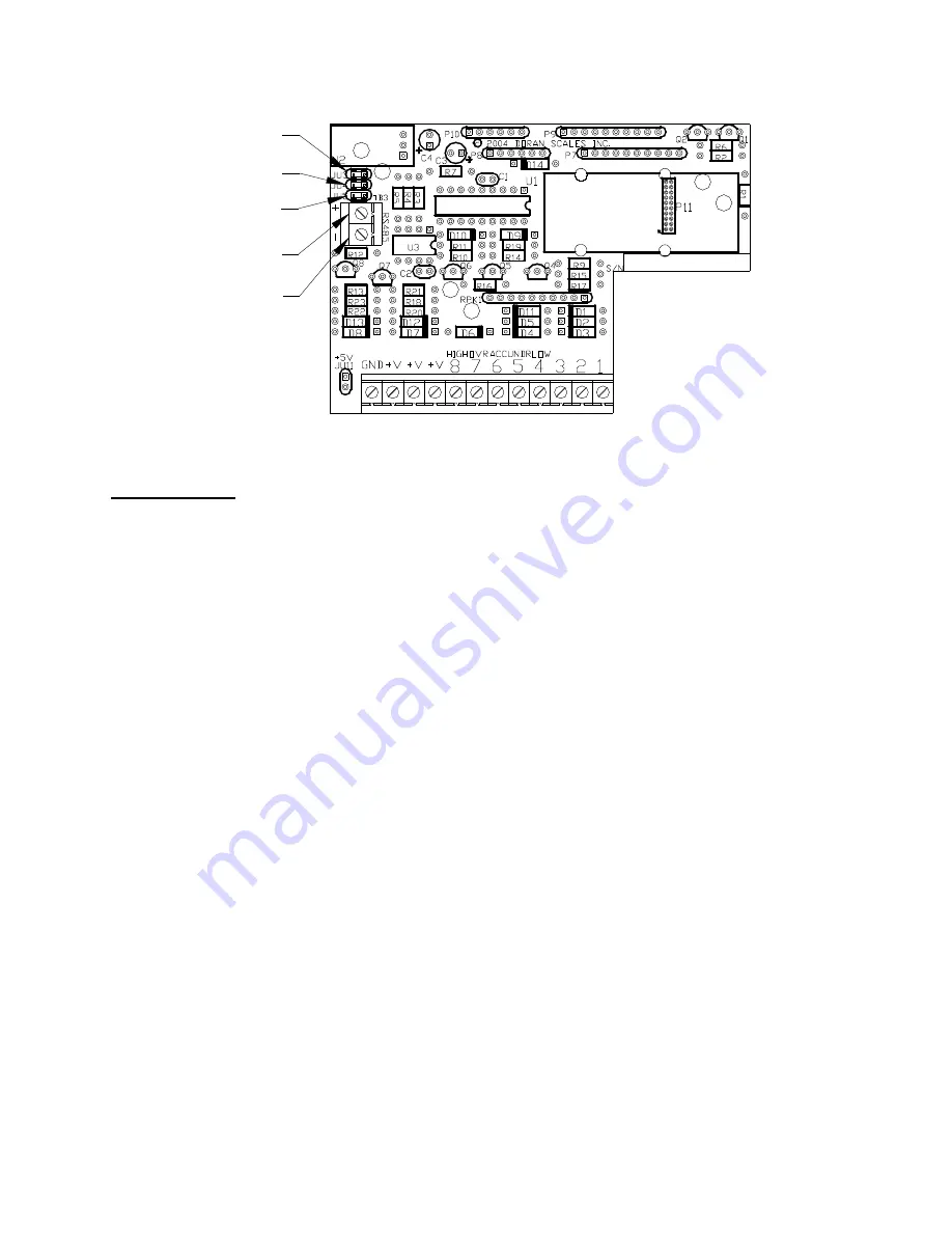
Fig. 15: Digital Output Board with RS485 Option
RS485 SETUP
The following section assumes that you are familiar with the operation of the parameter
setup menu. If you are unsure of any step while setting up RS485 operations, please
read previous sections in this Instruction Manual before continuing.
Setting up RS485 communications in the system requires that the scale be connected to
the RS485 bus. Using a two-wire data cable attached to TB3 on the Digital Output
option board makes this connection. See Fig. 15 and Fig. 16 for details on the necessary
connections. You will need to know and understand the operation of other RS485
devices in your system.
After setting up the cable, the scale must be configured to work with the RS485 bus.
Enter the setup mode and scroll through the setup menu until you come to the Serial
Data Output Handshaking and set it for RS485 mode. Next, press "UNITS" to step to
Scale (Bus) Address parameter. The scale will ship from the factory set for address "00".
Press "ZERO" to scroll up the value for bus address. Be sure to record the address you
selected. At this time, the RS485 buffer is activated.
Note:
If the Data Output Handshaking is not set to RS485, the scale will behave as if the
scale is communicating via RS232. This may be desired for a RS485 bus with one scale
on the bus or an application where communication with a single scale over a long
distance is required.
Once the scale address is set, select the "Data Output Mode." Doran Scales
recommends against using the Continuous Print Mode with RS485 because the buffer
will fill up quickly requiring frequent readings of the buffer. If you require an automatic
recording of weight data, then the Auto Print mode AP2 is recommended.
TB3, RS485
Data - (A)
JU5 120 ohm
termination resistor
JU3 1000 ohm
pull-up resistor
JU4 1000 ohm
pull-down resistor
TB3, RS485
Data + (B)
Summary of Contents for 2200 Series
Page 2: ...1 ...
Page 11: ...10 Scale Operation Fig 1 Model 2200 Front Panel Layout Fig 2 Model 2200B Front Panel Layout ...
Page 118: ...117 ...
Page 127: ...126 Fig 37 Mounting Dimensions ...
Page 136: ...135 ...


