G424F(FE) Service Manual
Chapter 5. Engine Management System (EMS)
153
Other system features include:
Tamper-Resistance
Special tools, equipment, knowledge, and
authorization are required to effect any changes to
the MI-07 system, thereby preventing unauthorized
personnel from making adjustments that will affect
performance or emissions.
Diagnostics
MI-07 is capable of monitoring and diagnosing
problems and faults within the system. These
include all sensor input hardware, control output
hardware, and control functions such as closed-loop
fuel control limits and adaptive learn limits. Upon
detecting a fault condition, the system notifies the
operator by illuminating the MIL and activating the
appropriate fault action. The action required by each
fault shall be programmable by the OEM customer
at the time the engine is calibrated.
Diagnostic information can be communicated
through both the service tool interface and the MIL
lamp. With the MIL lamp, it is possible to generate a
string of flashing codes that correspond to the fault
type. These diagnostics are generated only when
the engine is not running and the operator initiates a
diagnostic request sequence such as repeated
actuations of the pedal within a short period of time
following reset.
Limp Home Mode
The system is capable of "limp-home" mode in the
event of particular faults or failures in the system. In
limp-home mode the engine speed is approximately
1000 rpm at no load. A variety of fault conditions can
initiate limp-home mode. These fault conditions and
resulting actions are determined during calibration
and are OEM customer specific.
Service Tool
A scan tool/monitoring device is available to monitor
system operation and assist in diagnosis of system
faults This device monitors all sensor inputs, control
outputs, and diagnostic functions in sufficient detail
through a single access point to the SECM to allow
a qualified service technician to maintain the system.
This Mototune software (licensed by Mototron
Communication) is secure and requires a crypt-
token USB device to allow access to information.
LPG Fuel System Operation
The principles outlined below describe the operation
of MI-07 on an LPG fuel system.
An LPG fuel system consists of the following
components:
• Fuel filter (supplied by customer)
• Electric fuel lock-off solenoid valve
• Fuel pressure regulator/vaporizer
• Gas/Air mixer
• Miscellaneous customer-supplied hoses and
fittings
Fuel is stored in the customer-supplied LPG tank in
saturated liquid phase and enters the fuel system
from the tank as a liquid and at tank pressure. Fuel
passes through a high-pressure fuel filter and lock-
off solenoid, and is then vaporized and regulated
down to the appropriate pressure to supply the
mixer. The regulator controls the fuel pressure to the
gas/air mixer. The mixer meters fuel delivery based
upon airflow into the engine.
SECM
The Small Engine Control Module (SECM) controls
the LPG lock-off solenoid valve. The lock-off
solenoid is energized when fueling with LPG and the
engine is turning. The lock-off is de-energized when
engine rpm is not detected.
MI-07 LP Fuel Filter
The LP fuel filter of G424F engine is the same as
that of G424FE engine. See, “G424FE EMS
overview”
MI-07 Fuel Lock-Off (Electric)
The LP fuel lock-off of G424F engine is the same as
that of G424FE engine. See, “G424FE EMS
overview”
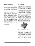
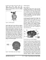
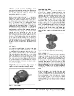
N-2001 Regulator/Converter
After passing through the electric fuel lock-off, liquid
propane enters the N-2001 regulator/converter
(Figure 4). The N-2001 functions as a fuel vaporizer,
converting liquid propane to vapor propane and as a
two-stage negative pressure regulator, supplying the
correct vapor propane fuel pressure to the mixer.
The regulator is normally closed requiring a vacuum
signal (negative pressure) to allow fuel to flow. This
is the second of three safety locks in the MI-07
system. If the engine stops, vacuum signal stops
and fuel flow will automatically stop when both the
Summary of Contents for D20G
Page 2: ......
Page 5: ...Specifications TORQUE SPECIFICATIONS SB2004E00 D e c 1 9 9 8 ...
Page 14: ......
Page 16: ......
Page 138: ...Diesel Engine Engine System 124 NOTE The crankshaft must rotate freely by hand 02900058 ...
Page 254: ......
Page 256: ......
Page 260: ......
Page 341: ...4TNV98 4TNE98 Diesel Engine Section 3 Engine 87 4TNE98 Engine Figure 6 1 ...
Page 423: ...4TNV98 4TNE98 Diesel Engine Section 4 Fuel System 169 Fuel System Components Figure 7 1 ...
Page 477: ...4TNV98 4TNE98 Diesel Engine Section 7 Starter Motor 223 Starter Motor Troubleshooting ...
Page 494: ...4TNV98 4TNE98 Diesel Engine Section 8 Troubleshooting 240 Troubleshooting Charts ...
Page 495: ...4TNV98 4TNE98 Diesel Engine Section 8 Troubleshooting 241 ...
Page 496: ...4TNV98 4TNE98 Diesel Engine Section 8 Troubleshooting 242 ...
Page 498: ...4TNV98 4TNE98 Diesel Engine Section 8 Troubleshooting 244 4TNE98 Engine ...
Page 499: ...Service Manual G424FE LP Engine G424F LP Gasoline Engine G20G G25G G30G SB4320E00 Jan 2008 ...
Page 500: ......
Page 502: ......
Page 529: ...G424F FE Service Manual Chapter 2 Recommended Maintenance 29 ...
Page 534: ...G424F FE Service Manual Chapter 3 Engine Mechanical System 34 MAIN BEARINGS 0 50 UNDERSIZE ...
Page 584: ...G424F FE Service Manual Chapter 3 Engine Mechanical System 84 ...
Page 729: ...G424F FE Service Manual 229 Chapter 8 Basic Troubleshooting ...
Page 731: ...G424F FE Service Manual 231 Chapter 8 Basic Troubleshooting ...
Page 806: ......
Page 808: ......
Page 810: ......
Page 820: ...Power Train System Operation 14 Hydraulic System ...
Page 822: ...Power Train System Operation 16 Hydraulic System ...
Page 824: ...Power Train System Operation 18 Hydraulic System ...
Page 826: ...Power Train System Operation 20 Hydraulic System ...
Page 856: ......
Page 858: ......
Page 860: ......
Page 930: ......
Page 932: ......
Page 934: ......
Page 936: ......
Page 1018: ......
Page 1023: ...A374081 01 ELECTRIC SCHEMATIC MODEL D20 25 30G EM0K2 EM0K3 Cummins B3 3 ...
Page 1024: ...A654030 00 ELECTRIC SCHEMATIC MODEL D20 25 30G EM0QM EM0QN Yanmar 4TNE98 Tier 3 ...
Page 1025: ...A604500 00 ELECTRIC SCHEMATIC MODEL G20 25 30G EM0QF EM0QG GM G424F Non Certi LP ...
Page 1026: ...A604510 00 ELECTRIC SCHEMATIC MODEL G20 25 30G EM0QH EM0QJ GM G424F Non Certi GAS ...
Page 1027: ...A604516 00 ELECTRIC SCHEMATIC MODEL G20 25 30G EM0QY EM0QZ GM G424FE Tier 3 LP ...
Page 1028: ......
Page 1030: ......
Page 1059: ...Safety Section 29 Lean away from the direction of fall Lean forward ...
Page 1071: ...General Section 41 Typical Example Side Shifter Serial Number If Equipped ...


