


Vehicle System
Disassembly & Assembly
77
b.
assembly of lift section.
1.
fix section by using a vice for
lateral(machined)faces not to be damaged.
2.
Install spool(2) into body(1) smoothly and
slowly. A direction of spool access to body is
same as that of spool disassembly.
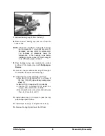
3.
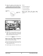
dust seals(4) put on the end of spool by using
a tool (Fig 8-9)
Note : be careful not to damage a dust seal,
as it could make an external leakage.
4.
after fixing the spool end, install seal
plate(3),spring retainer(6) and spring(8). And
tighten set screw(7) by 14NIm
NOTE
: make sure that set screws are
tightened by a exact torque. In case of
excessive torque, it could make inappropriate
spool motion. Incase of in sufficient torque
make a excessive drift of cylinder on neutral
position.
5.
install cap(5) and tighten two hex bolts(12)
by14N
•
m.
6.
put seal plate(3) on the end of spool and
tighten hex bolts(11) by 14N
•
m.
7.
install hex plug with O-ring by 35N
•
m.
8.
release a section from a vise, and install O-
ring(13), poppet(9) and spring(10) into lateral
face.
c.
assembly of tilt section.
1.
fix section by using a vice for
lateral(machined)faces not to be damaged.
2.
Install spool(2) into body(1) smoothly and
slowly. A direction of spool access to body is
same as that of spool disassembly.
3.
dust seals(6) put on the end of spool by using
a tool
Note : be careful not to damage a dust seal,
as it could make an external leakage.
4.
install pilot spool(3) and spring (4) into a
bottom of spool.
5.
after fixing the spool end, install seal plate(5),
spring retainer(8) and spring(10). And tighten
set screw(9) by 14N
•
m
NOTE
: make sure that set screws are
tightened by a exact torque. In case of
excessive torque, it could make inappropriate
spool motion. incase of in sufficient torque, it
could make a excessive drift of cylinder on
neutral position.
6.
install cap(7) and tighten two hex bolts(14)
by14N
•
m.
7.
put seal plate(5) on the end of spool and
tighten hex bolts(13) by 14N
•
m.
8.
release a section from a vise, and install O-
ring(13), poppet(9) and spring(10) into lateral
face.
Summary of Contents for D20G
Page 2: ......
Page 5: ...Specifications TORQUE SPECIFICATIONS SB2004E00 D e c 1 9 9 8 ...
Page 14: ......
Page 16: ......
Page 138: ...Diesel Engine Engine System 124 NOTE The crankshaft must rotate freely by hand 02900058 ...
Page 254: ......
Page 256: ......
Page 260: ......
Page 341: ...4TNV98 4TNE98 Diesel Engine Section 3 Engine 87 4TNE98 Engine Figure 6 1 ...
Page 423: ...4TNV98 4TNE98 Diesel Engine Section 4 Fuel System 169 Fuel System Components Figure 7 1 ...
Page 477: ...4TNV98 4TNE98 Diesel Engine Section 7 Starter Motor 223 Starter Motor Troubleshooting ...
Page 494: ...4TNV98 4TNE98 Diesel Engine Section 8 Troubleshooting 240 Troubleshooting Charts ...
Page 495: ...4TNV98 4TNE98 Diesel Engine Section 8 Troubleshooting 241 ...
Page 496: ...4TNV98 4TNE98 Diesel Engine Section 8 Troubleshooting 242 ...
Page 498: ...4TNV98 4TNE98 Diesel Engine Section 8 Troubleshooting 244 4TNE98 Engine ...
Page 499: ...Service Manual G424FE LP Engine G424F LP Gasoline Engine G20G G25G G30G SB4320E00 Jan 2008 ...
Page 500: ......
Page 502: ......
Page 529: ...G424F FE Service Manual Chapter 2 Recommended Maintenance 29 ...
Page 534: ...G424F FE Service Manual Chapter 3 Engine Mechanical System 34 MAIN BEARINGS 0 50 UNDERSIZE ...
Page 584: ...G424F FE Service Manual Chapter 3 Engine Mechanical System 84 ...
Page 729: ...G424F FE Service Manual 229 Chapter 8 Basic Troubleshooting ...
Page 731: ...G424F FE Service Manual 231 Chapter 8 Basic Troubleshooting ...
Page 806: ......
Page 808: ......
Page 810: ......
Page 820: ...Power Train System Operation 14 Hydraulic System ...
Page 822: ...Power Train System Operation 16 Hydraulic System ...
Page 824: ...Power Train System Operation 18 Hydraulic System ...
Page 826: ...Power Train System Operation 20 Hydraulic System ...
Page 856: ......
Page 858: ......
Page 860: ......
Page 930: ......
Page 932: ......
Page 934: ......
Page 936: ......
Page 1018: ......
Page 1023: ...A374081 01 ELECTRIC SCHEMATIC MODEL D20 25 30G EM0K2 EM0K3 Cummins B3 3 ...
Page 1024: ...A654030 00 ELECTRIC SCHEMATIC MODEL D20 25 30G EM0QM EM0QN Yanmar 4TNE98 Tier 3 ...
Page 1025: ...A604500 00 ELECTRIC SCHEMATIC MODEL G20 25 30G EM0QF EM0QG GM G424F Non Certi LP ...
Page 1026: ...A604510 00 ELECTRIC SCHEMATIC MODEL G20 25 30G EM0QH EM0QJ GM G424F Non Certi GAS ...
Page 1027: ...A604516 00 ELECTRIC SCHEMATIC MODEL G20 25 30G EM0QY EM0QZ GM G424FE Tier 3 LP ...
Page 1028: ......
Page 1030: ......
Page 1059: ...Safety Section 29 Lean away from the direction of fall Lean forward ...
Page 1071: ...General Section 41 Typical Example Side Shifter Serial Number If Equipped ...


