


G424F(FE) Service Manual
Chapter 9. Advanced Diagnostics
249
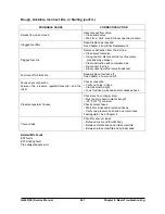
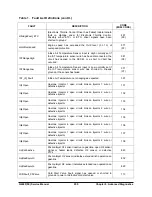
Fault Action Descriptions
Each fault detected by the SECM is stored in
memory (FIFO) and has a specific action or result
that takes place. Listed below are the descriptions of
each fault action.
Engine Shutdown:
The most severe action is an
Engine Shutdown. The MIL will light and the engine
will immediately shutdown, stopping spark, closing
the fuel lock-off closing, and turning off the fuel
pump and fuel injectors.
Delayed Engine Shutdown:
Some faults, such as
low oil pressure, will cause the MIL to illuminate for
30 seconds and then shut down the engine.
Cut Throttle:
The throttle moves to its default
position. The engine will run at idle but will not
accelerate.
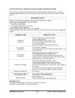
Cut Fuel:
Fuel flow will be turned off.
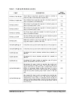
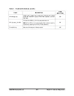
Turn on MIL
: The MIL will light by an active low
signal provided by the SECM, indicating a fault
condition. May illuminate with no other action or may
be combined with other actions, depending on which
fault is active.
Soft Rev Limit / Medium Rev Limit / Hard Rev
Limit:
System will follow various sequences to bring
engine speed back to acceptable levels.
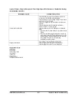
Level4 Power Limit / Level3 Power Limit / Level2
Power Limit / Level1 Power Limit:
The maximum
engine power output will be limited to one of four
possible levels. The engine power is calculated from
measured engine parameters (e.g. MAP, rpm, fuel
flow, etc).
Disable Gas O2 Control
: In LPG mode, closed loop
correction of air fuel ratio based on the Pre-catalyst
O2 sensor is disabled.
Disable Liquid O2 Control:
In Gasoline mode,
closed loop correction of air fuel ratio based on the
Pre-catalyst O2 sensor is disabled.
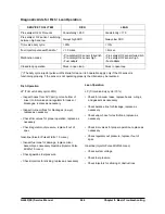
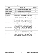
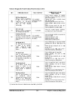
Fault List Definitions
All the analog sensors in the MI-07 system have
input sensor range faults. These are the coolant
temperature sensor, fuel temperature sensor,
throttle position sensors, pedal position sensors,
manifold pressure sensor, HEGO sensors, and
intake air temperature sensor. Signals to these
sensors are converted into digital counts by the
SECM. A low/high range sensor fault is normally set
when the converted digital counts reach the
minimum of 0 or the maximum of 1024 (1024 = 5.0
Vdc with ~ 204 counts per volt).
Additionally, the SECM includes software to learn
the actual range of the pedal position and throttle
position sensors in order to take full advantage of
the sensor range. Faults are set if the learned
values are outside of the normal expected range of
the sensor (e.g. APP1AdaptLoMin).
Summary of Contents for D20G
Page 2: ......
Page 5: ...Specifications TORQUE SPECIFICATIONS SB2004E00 D e c 1 9 9 8 ...
Page 14: ......
Page 16: ......
Page 138: ...Diesel Engine Engine System 124 NOTE The crankshaft must rotate freely by hand 02900058 ...
Page 254: ......
Page 256: ......
Page 260: ......
Page 341: ...4TNV98 4TNE98 Diesel Engine Section 3 Engine 87 4TNE98 Engine Figure 6 1 ...
Page 423: ...4TNV98 4TNE98 Diesel Engine Section 4 Fuel System 169 Fuel System Components Figure 7 1 ...
Page 477: ...4TNV98 4TNE98 Diesel Engine Section 7 Starter Motor 223 Starter Motor Troubleshooting ...
Page 494: ...4TNV98 4TNE98 Diesel Engine Section 8 Troubleshooting 240 Troubleshooting Charts ...
Page 495: ...4TNV98 4TNE98 Diesel Engine Section 8 Troubleshooting 241 ...
Page 496: ...4TNV98 4TNE98 Diesel Engine Section 8 Troubleshooting 242 ...
Page 498: ...4TNV98 4TNE98 Diesel Engine Section 8 Troubleshooting 244 4TNE98 Engine ...
Page 499: ...Service Manual G424FE LP Engine G424F LP Gasoline Engine G20G G25G G30G SB4320E00 Jan 2008 ...
Page 500: ......
Page 502: ......
Page 529: ...G424F FE Service Manual Chapter 2 Recommended Maintenance 29 ...
Page 534: ...G424F FE Service Manual Chapter 3 Engine Mechanical System 34 MAIN BEARINGS 0 50 UNDERSIZE ...
Page 584: ...G424F FE Service Manual Chapter 3 Engine Mechanical System 84 ...
Page 729: ...G424F FE Service Manual 229 Chapter 8 Basic Troubleshooting ...
Page 731: ...G424F FE Service Manual 231 Chapter 8 Basic Troubleshooting ...
Page 806: ......
Page 808: ......
Page 810: ......
Page 820: ...Power Train System Operation 14 Hydraulic System ...
Page 822: ...Power Train System Operation 16 Hydraulic System ...
Page 824: ...Power Train System Operation 18 Hydraulic System ...
Page 826: ...Power Train System Operation 20 Hydraulic System ...
Page 856: ......
Page 858: ......
Page 860: ......
Page 930: ......
Page 932: ......
Page 934: ......
Page 936: ......
Page 1018: ......
Page 1023: ...A374081 01 ELECTRIC SCHEMATIC MODEL D20 25 30G EM0K2 EM0K3 Cummins B3 3 ...
Page 1024: ...A654030 00 ELECTRIC SCHEMATIC MODEL D20 25 30G EM0QM EM0QN Yanmar 4TNE98 Tier 3 ...
Page 1025: ...A604500 00 ELECTRIC SCHEMATIC MODEL G20 25 30G EM0QF EM0QG GM G424F Non Certi LP ...
Page 1026: ...A604510 00 ELECTRIC SCHEMATIC MODEL G20 25 30G EM0QH EM0QJ GM G424F Non Certi GAS ...
Page 1027: ...A604516 00 ELECTRIC SCHEMATIC MODEL G20 25 30G EM0QY EM0QZ GM G424FE Tier 3 LP ...
Page 1028: ......
Page 1030: ......
Page 1059: ...Safety Section 29 Lean away from the direction of fall Lean forward ...
Page 1071: ...General Section 41 Typical Example Side Shifter Serial Number If Equipped ...


