


Vehicle System
System Operation
29
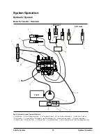
Oil Flow
The oil from the priority valve flows through inlet (4).
When the steering wheel is stationary (NEUTRAL),
the oil is stopped by spool (1). The oil can not flow
through the steering gear to the steering cylinder
until the steering wheel is turned.
The steering wheel is connected to spool (1) by a
shaft assembly and splines. When the steering
wheel is turned, spool (1) turns a small amount until
springs(7) are compressed. Then, sleeve (2) starts
to turn.
As long as the steering wheel is turned, the spool
and sleeve both turn as a unit, but they turn a few
degrees apart.
When the spool and sleeve are a few degrees apart,
oil passages are opened between them. This lets
the pump oil from inlet (4) flow through passages in
body(11) to the metering section.
When the steering wheel is turned, pin (8) turns with
the sleeve and causes drive (12) to turn also. The
drive causes a rotation of gear (5) inside gear
(6).This rotation of the gear sends a controlled
(metered) flow of pilot oil back through body (11).
This oil flows to port (9) or (10) and then to the
steering cylinder. Port (9) or (10), that is not used for
pressure oil to the steering cylinder, is used for
return oil from the other end of the steering cylinder.
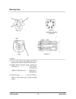
Pump Gears In Metering Section
(5) Internal pump gear. (6) External pump gear. (8) Pin.(12) Drive.
If the steering wheel rotation is stopped, springs (7)
will move sleeve (2) back in alignment with spool (1)
(NEUTRAL position). This will close passages
between the metering section and control section
and the steering gear will be in the NEUTRAL
position.
When the engine is off, the steering gear can be
manually operated. The control section will work as
a pump. The oil that is returned from the steering
cylinder is not returned to the tank. The suction of
the control section will open an internal check valve
and let return oil from the steering cylinder go to the
inlet side of the control section. During power
operation, supply pressure keeps the check valve
closed.
Summary of Contents for D20G
Page 2: ......
Page 5: ...Specifications TORQUE SPECIFICATIONS SB2004E00 D e c 1 9 9 8 ...
Page 14: ......
Page 16: ......
Page 138: ...Diesel Engine Engine System 124 NOTE The crankshaft must rotate freely by hand 02900058 ...
Page 254: ......
Page 256: ......
Page 260: ......
Page 341: ...4TNV98 4TNE98 Diesel Engine Section 3 Engine 87 4TNE98 Engine Figure 6 1 ...
Page 423: ...4TNV98 4TNE98 Diesel Engine Section 4 Fuel System 169 Fuel System Components Figure 7 1 ...
Page 477: ...4TNV98 4TNE98 Diesel Engine Section 7 Starter Motor 223 Starter Motor Troubleshooting ...
Page 494: ...4TNV98 4TNE98 Diesel Engine Section 8 Troubleshooting 240 Troubleshooting Charts ...
Page 495: ...4TNV98 4TNE98 Diesel Engine Section 8 Troubleshooting 241 ...
Page 496: ...4TNV98 4TNE98 Diesel Engine Section 8 Troubleshooting 242 ...
Page 498: ...4TNV98 4TNE98 Diesel Engine Section 8 Troubleshooting 244 4TNE98 Engine ...
Page 499: ...Service Manual G424FE LP Engine G424F LP Gasoline Engine G20G G25G G30G SB4320E00 Jan 2008 ...
Page 500: ......
Page 502: ......
Page 529: ...G424F FE Service Manual Chapter 2 Recommended Maintenance 29 ...
Page 534: ...G424F FE Service Manual Chapter 3 Engine Mechanical System 34 MAIN BEARINGS 0 50 UNDERSIZE ...
Page 584: ...G424F FE Service Manual Chapter 3 Engine Mechanical System 84 ...
Page 729: ...G424F FE Service Manual 229 Chapter 8 Basic Troubleshooting ...
Page 731: ...G424F FE Service Manual 231 Chapter 8 Basic Troubleshooting ...
Page 806: ......
Page 808: ......
Page 810: ......
Page 820: ...Power Train System Operation 14 Hydraulic System ...
Page 822: ...Power Train System Operation 16 Hydraulic System ...
Page 824: ...Power Train System Operation 18 Hydraulic System ...
Page 826: ...Power Train System Operation 20 Hydraulic System ...
Page 856: ......
Page 858: ......
Page 860: ......
Page 930: ......
Page 932: ......
Page 934: ......
Page 936: ......
Page 1018: ......
Page 1023: ...A374081 01 ELECTRIC SCHEMATIC MODEL D20 25 30G EM0K2 EM0K3 Cummins B3 3 ...
Page 1024: ...A654030 00 ELECTRIC SCHEMATIC MODEL D20 25 30G EM0QM EM0QN Yanmar 4TNE98 Tier 3 ...
Page 1025: ...A604500 00 ELECTRIC SCHEMATIC MODEL G20 25 30G EM0QF EM0QG GM G424F Non Certi LP ...
Page 1026: ...A604510 00 ELECTRIC SCHEMATIC MODEL G20 25 30G EM0QH EM0QJ GM G424F Non Certi GAS ...
Page 1027: ...A604516 00 ELECTRIC SCHEMATIC MODEL G20 25 30G EM0QY EM0QZ GM G424FE Tier 3 LP ...
Page 1028: ......
Page 1030: ......
Page 1059: ...Safety Section 29 Lean away from the direction of fall Lean forward ...
Page 1071: ...General Section 41 Typical Example Side Shifter Serial Number If Equipped ...


