


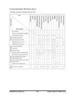


G424F(FE) Service Manual
240
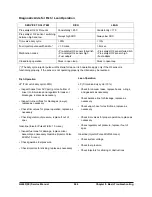
Chapter 8. Basic Troubleshooting
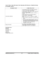
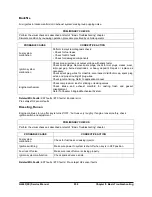
Rough, Unstable, Incorrect Idle, or Stalling
Engine cranks OK, but does not start for a long time. Does eventually run, or may start but immediately dies.
PRELIMINARY CHECKS
Perform the visual checks as described at start of “Basic Troubleshooting” chapter.
Check for vacuum leaks.
Check that SECM grounds are clean and tight. See SECM wiring diagram
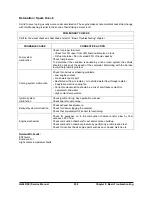
PROBABLE CAUSE
CORRECTIVE ACTION
Fuel system
malfunction
Monitor oxygen feedback to help identify the cause of the problem. If
the system is running lean or if the system is running rich evaluate
further i.e. dither valve duty cycle and injector pulse width.
Check for incorrect minimum idle speed that may be caused by foreign
material accumulation in the throttle bore, on the throttle valve, or on
the throttle shaft.
Check that the injectors are clean and functioning.
Check for liquid fuel in propane pressure regulator hose. If fuel is
present, replace regulator assembly.
The pre-catalyst oxygen (O2) sensor should respond quickly to
different throttle positions. If it does not, then check the pre-catalyst O2
sensor for contamination. If the pre-catalyst O2 sensor is aged or
contaminated, the SECM will not deliver correct amount of fuel,
resulting in a drivability problem.
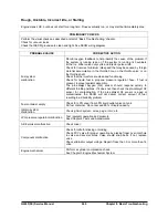
Fuel container empty
Check for LPG vapor from LPG liquid outlet valve on tank.
Fill fuel container. Do not exceed 80% of liquid capacity.
Ignition system
malfunction
Check ignition system; wires, plugs, rotor, etc.
LPG pressure regulator malfunction
Test regulator operation and pressure.
See Chapter 6 Tests and Adjustments
Air/fuel mixer malfunction
Check mixer.
Component malfunction
Check throttle for sticking or binding.
Check PCV valve for proper operation by placing finger over inlet hole
in valve end several times. Valve should snap back. If not, replace
valve.
Check alternator output voltage. Repair if less than 9 or more than 16
volts.
Engine mechanical
Perform a cylinder compression check.
See Chapter 3 Engine Mechanical System.
Summary of Contents for D20G
Page 2: ......
Page 5: ...Specifications TORQUE SPECIFICATIONS SB2004E00 D e c 1 9 9 8 ...
Page 14: ......
Page 16: ......
Page 138: ...Diesel Engine Engine System 124 NOTE The crankshaft must rotate freely by hand 02900058 ...
Page 254: ......
Page 256: ......
Page 260: ......
Page 341: ...4TNV98 4TNE98 Diesel Engine Section 3 Engine 87 4TNE98 Engine Figure 6 1 ...
Page 423: ...4TNV98 4TNE98 Diesel Engine Section 4 Fuel System 169 Fuel System Components Figure 7 1 ...
Page 477: ...4TNV98 4TNE98 Diesel Engine Section 7 Starter Motor 223 Starter Motor Troubleshooting ...
Page 494: ...4TNV98 4TNE98 Diesel Engine Section 8 Troubleshooting 240 Troubleshooting Charts ...
Page 495: ...4TNV98 4TNE98 Diesel Engine Section 8 Troubleshooting 241 ...
Page 496: ...4TNV98 4TNE98 Diesel Engine Section 8 Troubleshooting 242 ...
Page 498: ...4TNV98 4TNE98 Diesel Engine Section 8 Troubleshooting 244 4TNE98 Engine ...
Page 499: ...Service Manual G424FE LP Engine G424F LP Gasoline Engine G20G G25G G30G SB4320E00 Jan 2008 ...
Page 500: ......
Page 502: ......
Page 529: ...G424F FE Service Manual Chapter 2 Recommended Maintenance 29 ...
Page 534: ...G424F FE Service Manual Chapter 3 Engine Mechanical System 34 MAIN BEARINGS 0 50 UNDERSIZE ...
Page 584: ...G424F FE Service Manual Chapter 3 Engine Mechanical System 84 ...
Page 729: ...G424F FE Service Manual 229 Chapter 8 Basic Troubleshooting ...
Page 731: ...G424F FE Service Manual 231 Chapter 8 Basic Troubleshooting ...
Page 806: ......
Page 808: ......
Page 810: ......
Page 820: ...Power Train System Operation 14 Hydraulic System ...
Page 822: ...Power Train System Operation 16 Hydraulic System ...
Page 824: ...Power Train System Operation 18 Hydraulic System ...
Page 826: ...Power Train System Operation 20 Hydraulic System ...
Page 856: ......
Page 858: ......
Page 860: ......
Page 930: ......
Page 932: ......
Page 934: ......
Page 936: ......
Page 1018: ......
Page 1023: ...A374081 01 ELECTRIC SCHEMATIC MODEL D20 25 30G EM0K2 EM0K3 Cummins B3 3 ...
Page 1024: ...A654030 00 ELECTRIC SCHEMATIC MODEL D20 25 30G EM0QM EM0QN Yanmar 4TNE98 Tier 3 ...
Page 1025: ...A604500 00 ELECTRIC SCHEMATIC MODEL G20 25 30G EM0QF EM0QG GM G424F Non Certi LP ...
Page 1026: ...A604510 00 ELECTRIC SCHEMATIC MODEL G20 25 30G EM0QH EM0QJ GM G424F Non Certi GAS ...
Page 1027: ...A604516 00 ELECTRIC SCHEMATIC MODEL G20 25 30G EM0QY EM0QZ GM G424FE Tier 3 LP ...
Page 1028: ......
Page 1030: ......
Page 1059: ...Safety Section 29 Lean away from the direction of fall Lean forward ...
Page 1071: ...General Section 41 Typical Example Side Shifter Serial Number If Equipped ...


