


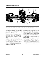


Power Train
Testing And Adjusting
22
Testing and Adjusting
Troubleshooting
Troubleshooting can be difficult. A list of possible
problems and corrections is on the pages that follow.
This list of problems and corrections will only give an
indication of where a problem can be and what
repairs are needed. Normally, more or other repair
work is needed beyond the recommendations on the
list. Remember that a problem is not necessarily
caused only by one part, but by the relation of one
part with other parts. This list can not give all
possible problems and corrections. The serviceman
must find the problem and its source, then make the
necessary repairs.
Always make visual checks first. Check the
operation of the machine and then check with
instruments.
WARNING
When testing and adjusting the power train,
move the machine to an area clear of
obstructions, and with safe ventilation for the
exhaust. When drive wheels are off the ground
for testing, keep away from wheels that are in
rotation.
Visual Checks
1.
Check the oil level in the transmission with the
engine running and with the transmission in
NEUTRAL.
2.
Check all oil lines, hoses and connections for
leaks and damage. Look for oil on the ground
under the machine.
3.
Move the lever for the direction control to
REVERSE and FORWARD positions. The detents
must be felt in each position.
4.
Check the oil in the transmission for loose
particles.
a.
Bronze-colored particles give an indication of a
clutch failure.
b.
Shiny steel particles in the filter give an
indication of a pump failure.
c.
Rubber particles give an indication of a seal
failure or hose failure.
If you find metal or rubber particles, all components
of the hydraulic and lubrication systems must be
washed clean. Do not use parts with damage. Use
new parts.
Checks During Operation
NOTICE
Before these checks are started, fill the transmission
with oil to the correct level.
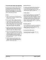
Power Shift Transmission
With the engine running and brakes on, move the
selector lever to all positions. The detents must be
felt in each position.
Operate the machine in each direction. Make note of
all noises that are not normal and find their sources.
If the operation is not correct, make reference to the
CHECK LIST DURING OPERATION for “problems”
and “probable causes”.
Check List During Operation
Problem: Transmission does not operate in
either direction or does not engage (slips) in all
directions.
Probable Cause :
1.
Low oil pressure caused by :
a.
Low oil level.
b.
Inching control valve linkage loose, broken or
adjustment not correct.
c.
Failure of the oil pump.
d.
Leakage inside the transmission.
e.
Pressure regulator valve stuck.
2.
Mechanical failure in transmission.
3.
Failure of the bevel pinion or the ring gear.
Problem: Transmission does not shift.
Probable Cause:
1.
Low oil pressure.
2.
Pressure regulator valve will not move (stuck).
3.
Control linkage worn, broken or adjustment is not
correct.
Summary of Contents for D20G
Page 2: ......
Page 5: ...Specifications TORQUE SPECIFICATIONS SB2004E00 D e c 1 9 9 8 ...
Page 14: ......
Page 16: ......
Page 138: ...Diesel Engine Engine System 124 NOTE The crankshaft must rotate freely by hand 02900058 ...
Page 254: ......
Page 256: ......
Page 260: ......
Page 341: ...4TNV98 4TNE98 Diesel Engine Section 3 Engine 87 4TNE98 Engine Figure 6 1 ...
Page 423: ...4TNV98 4TNE98 Diesel Engine Section 4 Fuel System 169 Fuel System Components Figure 7 1 ...
Page 477: ...4TNV98 4TNE98 Diesel Engine Section 7 Starter Motor 223 Starter Motor Troubleshooting ...
Page 494: ...4TNV98 4TNE98 Diesel Engine Section 8 Troubleshooting 240 Troubleshooting Charts ...
Page 495: ...4TNV98 4TNE98 Diesel Engine Section 8 Troubleshooting 241 ...
Page 496: ...4TNV98 4TNE98 Diesel Engine Section 8 Troubleshooting 242 ...
Page 498: ...4TNV98 4TNE98 Diesel Engine Section 8 Troubleshooting 244 4TNE98 Engine ...
Page 499: ...Service Manual G424FE LP Engine G424F LP Gasoline Engine G20G G25G G30G SB4320E00 Jan 2008 ...
Page 500: ......
Page 502: ......
Page 529: ...G424F FE Service Manual Chapter 2 Recommended Maintenance 29 ...
Page 534: ...G424F FE Service Manual Chapter 3 Engine Mechanical System 34 MAIN BEARINGS 0 50 UNDERSIZE ...
Page 584: ...G424F FE Service Manual Chapter 3 Engine Mechanical System 84 ...
Page 729: ...G424F FE Service Manual 229 Chapter 8 Basic Troubleshooting ...
Page 731: ...G424F FE Service Manual 231 Chapter 8 Basic Troubleshooting ...
Page 806: ......
Page 808: ......
Page 810: ......
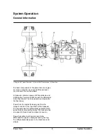
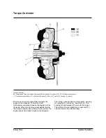
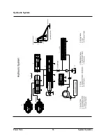
Page 820: ...Power Train System Operation 14 Hydraulic System ...
Page 822: ...Power Train System Operation 16 Hydraulic System ...
Page 824: ...Power Train System Operation 18 Hydraulic System ...
Page 826: ...Power Train System Operation 20 Hydraulic System ...
Page 856: ......
Page 858: ......
Page 860: ......
Page 930: ......
Page 932: ......
Page 934: ......
Page 936: ......
Page 1018: ......
Page 1023: ...A374081 01 ELECTRIC SCHEMATIC MODEL D20 25 30G EM0K2 EM0K3 Cummins B3 3 ...
Page 1024: ...A654030 00 ELECTRIC SCHEMATIC MODEL D20 25 30G EM0QM EM0QN Yanmar 4TNE98 Tier 3 ...
Page 1025: ...A604500 00 ELECTRIC SCHEMATIC MODEL G20 25 30G EM0QF EM0QG GM G424F Non Certi LP ...
Page 1026: ...A604510 00 ELECTRIC SCHEMATIC MODEL G20 25 30G EM0QH EM0QJ GM G424F Non Certi GAS ...
Page 1027: ...A604516 00 ELECTRIC SCHEMATIC MODEL G20 25 30G EM0QY EM0QZ GM G424FE Tier 3 LP ...
Page 1028: ......
Page 1030: ......
Page 1059: ...Safety Section 29 Lean away from the direction of fall Lean forward ...
Page 1071: ...General Section 41 Typical Example Side Shifter Serial Number If Equipped ...


