


G424F(FE) Service Manual
Chapter 4. Engine Electrical System
117
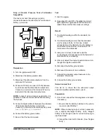
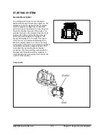
The result of these switches and relays is to permit a
5 amp dash-mounted switch to turn on a 500 to
1000amp motor used to crank an engine. Battery
voltage (power) available during cranking varies
according to the temperature of the batteries. The
following chart is a guide as to what to expect from a
normal system.
TYPICALSYSTEM VOLTAGE DURING
CRANKING AT VARIOUS AMBIENT
TEMPERATURES
Temperature 12V
System
-23 to -7 C (-10 to 20 F)
6 to 8 Volts
-7 to 10 C (20 to 50 F)
7 to 9 Volts
10 to 27 C (50 to 80 F)
8 to 10 Volts
Figure 1
The next chart shows maximum acceptable voltage
loss in the high current battery circuit feeding the
starting motor. These values are maximums for
machines of approximately 2000 SMH and up.
Newer machines would be less than those shown.
MAXIMUM ACCEPTABLE SYSTEM VOLTAGE
DROPS DURING CRANKING
Circuit 12V
System
Battery(-) post to starting motor (-)
terminal
0.7 Volts
Battery (+) post to solenoid (+)
terminal
0.5 Volts
Solenoid Bat terminal to solenoid
Mtr terminal
0.4 Volts
Figure 2
Voltages greater than those shown are most often
caused by loose and/or corroded connections or
defective switch contacts.
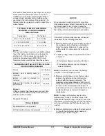
Diagnosis Procedure
TOOLS NEEDED
Digital Multimeter or Equivalent
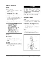
1
DC Clamp-On Ammeter or Equivalent
1
NOTICE
Do not operate the starting motor for more than
30seconds at a time. After 30 seconds, the cranking
must be stopped for two minutes to allow the
starting motor to cool. This will prevent damage to
the starting motor due to excessive heat buildup.
If the starting motor cranks real slow or does not
crank at all, do the following procedure:
1.
Measure battery voltage at the battery posts with
the multimeter while cranking or attempting to
crank the engine. Make sure to measure the
battery posts. Do not measure the cable post
clamps.
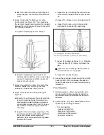
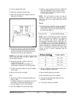
2.
Is battery voltage equal to or greater than shown
in Figure 1?
• If the battery voltage is correct, go to Step 3.
• If the battery voltage is too low, Charge or
replace the battery.
NOTE:
Alow battery can be caused by battery
condition or a shorted starting motor.
3.
Measure current draw on the (+) battery cable
between the battery and the starting motor
solenoid with the clamp-on ammeter. The
maximum current draw allowed is 350 Amp. At
temperatures below27°C (80°F), the voltage will
be less and the current draw will be higer. If
current draw is too much, the starting motor has a
problem and must be removed for repair or
replacement.
NOTE:
If voltage at the battery post is within
approximately 2 volts of the lowest value in the
applicable temperature range of Figure1 and if the
large starting motor cables get hot, then the starting
motor has a problem and the Ammeter test is not
needed.
4.
Measure starting motor voltage from test point (4)
to (5) with the multimeter while cranking or
attempting to crank the engine.
Summary of Contents for D20G
Page 2: ......
Page 5: ...Specifications TORQUE SPECIFICATIONS SB2004E00 D e c 1 9 9 8 ...
Page 14: ......
Page 16: ......
Page 138: ...Diesel Engine Engine System 124 NOTE The crankshaft must rotate freely by hand 02900058 ...
Page 254: ......
Page 256: ......
Page 260: ......
Page 341: ...4TNV98 4TNE98 Diesel Engine Section 3 Engine 87 4TNE98 Engine Figure 6 1 ...
Page 423: ...4TNV98 4TNE98 Diesel Engine Section 4 Fuel System 169 Fuel System Components Figure 7 1 ...
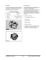
Page 477: ...4TNV98 4TNE98 Diesel Engine Section 7 Starter Motor 223 Starter Motor Troubleshooting ...
Page 494: ...4TNV98 4TNE98 Diesel Engine Section 8 Troubleshooting 240 Troubleshooting Charts ...
Page 495: ...4TNV98 4TNE98 Diesel Engine Section 8 Troubleshooting 241 ...
Page 496: ...4TNV98 4TNE98 Diesel Engine Section 8 Troubleshooting 242 ...
Page 498: ...4TNV98 4TNE98 Diesel Engine Section 8 Troubleshooting 244 4TNE98 Engine ...
Page 499: ...Service Manual G424FE LP Engine G424F LP Gasoline Engine G20G G25G G30G SB4320E00 Jan 2008 ...
Page 500: ......
Page 502: ......
Page 529: ...G424F FE Service Manual Chapter 2 Recommended Maintenance 29 ...
Page 534: ...G424F FE Service Manual Chapter 3 Engine Mechanical System 34 MAIN BEARINGS 0 50 UNDERSIZE ...
Page 584: ...G424F FE Service Manual Chapter 3 Engine Mechanical System 84 ...
Page 729: ...G424F FE Service Manual 229 Chapter 8 Basic Troubleshooting ...
Page 731: ...G424F FE Service Manual 231 Chapter 8 Basic Troubleshooting ...
Page 806: ......
Page 808: ......
Page 810: ......
Page 820: ...Power Train System Operation 14 Hydraulic System ...
Page 822: ...Power Train System Operation 16 Hydraulic System ...
Page 824: ...Power Train System Operation 18 Hydraulic System ...
Page 826: ...Power Train System Operation 20 Hydraulic System ...
Page 856: ......
Page 858: ......
Page 860: ......
Page 930: ......
Page 932: ......
Page 934: ......
Page 936: ......
Page 1018: ......
Page 1023: ...A374081 01 ELECTRIC SCHEMATIC MODEL D20 25 30G EM0K2 EM0K3 Cummins B3 3 ...
Page 1024: ...A654030 00 ELECTRIC SCHEMATIC MODEL D20 25 30G EM0QM EM0QN Yanmar 4TNE98 Tier 3 ...
Page 1025: ...A604500 00 ELECTRIC SCHEMATIC MODEL G20 25 30G EM0QF EM0QG GM G424F Non Certi LP ...
Page 1026: ...A604510 00 ELECTRIC SCHEMATIC MODEL G20 25 30G EM0QH EM0QJ GM G424F Non Certi GAS ...
Page 1027: ...A604516 00 ELECTRIC SCHEMATIC MODEL G20 25 30G EM0QY EM0QZ GM G424FE Tier 3 LP ...
Page 1028: ......
Page 1030: ......
Page 1059: ...Safety Section 29 Lean away from the direction of fall Lean forward ...
Page 1071: ...General Section 41 Typical Example Side Shifter Serial Number If Equipped ...


