


G424F(FE) Service Manual
Chapter 3. Engine Mechanical System
97
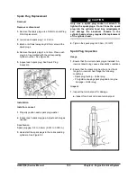
47.
A new seal ring in the crankcase phase and
reference sensor.
48.
Crankshaft phase and reference sensor in the
cylinder block and attaching bolt; use a Torx E10
wrench and torque wrench to tighten.
Tighten
•
Bolt: 4 – 8 N
·
m (3 – 5.8 lb
·
ft.).
49.
Spark plugs, with a proper wrench
.
50.
Power steering pump and attaching bolts, with a
13-mm socket wrench and torque wrench.
Tighten
•
Bolts: 20 – 30 N
·
m (15 – 22 lb
·
ft.).
51.
Generator and attaching bolts, with a 14-mm
socket wrench and torque wrench; tighten.
Tighten
•
Bolts: 20 – 30 N
·
m (15 – 22 lb
·
ft.).
52.
Belt automatic tensioner with attaching bolt, with
a 16-mm socket wrench and torque wrench;
tighten.
Tighten
•
Bolt: 18 – 22 N
·
m (13 – 16 lb
·
ft.).
53.
Clutch; see “Clutch – Installation”, section 7C.
54.
Engine assembly; see “Engine Assembly –
Installation”, in this section.
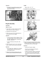
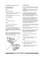
Pistons and/or Connecting Rods
Removal
Remove or disconnect
1.
Engine and transmission assembly, as per
instructions under “Engine and Transmission
Assembly – Removal”, in this section.
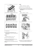
2.
Clutch; see “Clutch – Removal”, on Section 7C.
3.
Power steering pump attaching bolts, with a
13-mm box-end wrench; remove the pump.
4.
Generator attaching bolt, with a 14-mm box-end
wrench; remove the generator.
5.
Cylinder head; see “Cylinder Head – Removal”, in
this section.
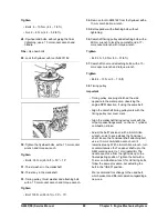
6.
Turn the engine 180° to have access to the
engine crankcase.
7.
Engine crankcase attaching bolts, with a Torx E12
wrench, extension and handle; remove the
crankcase from the engine.
8.
Oil strainer attaching bolt, with a 10-mm socket
wrench and handle. Remove the oil strainer bolts
and Torx E12 wrench. Loosen the attaching bolt
from the oil strainer stem.
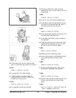
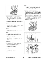
9.
Baffle plate and balancer attaching bolts, with a
Torx E12 wrench and handle; remove the baffle
plate and balancer.
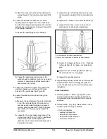
10.
Install two flywheel attaching bolts to the
crankshaft to rotate the latter and ease the
access to the connecting rod attaching bolts.
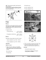
11.
With a punch identify the connecting rod bearing
and connecting rod, according to the
corresponding cylinder.
12.
Turn the crankshaft until the first and fourth
connecting rod remains with the attaching bolts
upward.
13.
First and fourth connecting rod bearing attaching
bolts, with a 14-mm wrench, extension and
handle; remove the connecting rod caps.
14.
Install tool T-9806681 in the connecting rod and
remove the piston.
15.
Turn the crankshaft until the second and third
connecting rods have the attaching bolt turned
upward.
Summary of Contents for D20G
Page 2: ......
Page 5: ...Specifications TORQUE SPECIFICATIONS SB2004E00 D e c 1 9 9 8 ...
Page 14: ......
Page 16: ......
Page 138: ...Diesel Engine Engine System 124 NOTE The crankshaft must rotate freely by hand 02900058 ...
Page 254: ......
Page 256: ......
Page 260: ......
Page 341: ...4TNV98 4TNE98 Diesel Engine Section 3 Engine 87 4TNE98 Engine Figure 6 1 ...
Page 423: ...4TNV98 4TNE98 Diesel Engine Section 4 Fuel System 169 Fuel System Components Figure 7 1 ...
Page 477: ...4TNV98 4TNE98 Diesel Engine Section 7 Starter Motor 223 Starter Motor Troubleshooting ...
Page 494: ...4TNV98 4TNE98 Diesel Engine Section 8 Troubleshooting 240 Troubleshooting Charts ...
Page 495: ...4TNV98 4TNE98 Diesel Engine Section 8 Troubleshooting 241 ...
Page 496: ...4TNV98 4TNE98 Diesel Engine Section 8 Troubleshooting 242 ...
Page 498: ...4TNV98 4TNE98 Diesel Engine Section 8 Troubleshooting 244 4TNE98 Engine ...
Page 499: ...Service Manual G424FE LP Engine G424F LP Gasoline Engine G20G G25G G30G SB4320E00 Jan 2008 ...
Page 500: ......
Page 502: ......
Page 529: ...G424F FE Service Manual Chapter 2 Recommended Maintenance 29 ...
Page 534: ...G424F FE Service Manual Chapter 3 Engine Mechanical System 34 MAIN BEARINGS 0 50 UNDERSIZE ...
Page 584: ...G424F FE Service Manual Chapter 3 Engine Mechanical System 84 ...
Page 729: ...G424F FE Service Manual 229 Chapter 8 Basic Troubleshooting ...
Page 731: ...G424F FE Service Manual 231 Chapter 8 Basic Troubleshooting ...
Page 806: ......
Page 808: ......
Page 810: ......
Page 820: ...Power Train System Operation 14 Hydraulic System ...
Page 822: ...Power Train System Operation 16 Hydraulic System ...
Page 824: ...Power Train System Operation 18 Hydraulic System ...
Page 826: ...Power Train System Operation 20 Hydraulic System ...
Page 856: ......
Page 858: ......
Page 860: ......
Page 930: ......
Page 932: ......
Page 934: ......
Page 936: ......
Page 1018: ......
Page 1023: ...A374081 01 ELECTRIC SCHEMATIC MODEL D20 25 30G EM0K2 EM0K3 Cummins B3 3 ...
Page 1024: ...A654030 00 ELECTRIC SCHEMATIC MODEL D20 25 30G EM0QM EM0QN Yanmar 4TNE98 Tier 3 ...
Page 1025: ...A604500 00 ELECTRIC SCHEMATIC MODEL G20 25 30G EM0QF EM0QG GM G424F Non Certi LP ...
Page 1026: ...A604510 00 ELECTRIC SCHEMATIC MODEL G20 25 30G EM0QH EM0QJ GM G424F Non Certi GAS ...
Page 1027: ...A604516 00 ELECTRIC SCHEMATIC MODEL G20 25 30G EM0QY EM0QZ GM G424FE Tier 3 LP ...
Page 1028: ......
Page 1030: ......
Page 1059: ...Safety Section 29 Lean away from the direction of fall Lean forward ...
Page 1071: ...General Section 41 Typical Example Side Shifter Serial Number If Equipped ...


