


Operation Section
- 64 -
Electronic Controlled Spark-Ignition Engines
G424FE Engine
EMS (Engine management system) of G424FE
engine is a closed loop system utilizing a 3-way
catalytic muffler to reduce the emission level in the
exhaust gas. In order to obtain maximum effect from
the catalyst, an accurate control of the air fuel ratio
is required. A small engine control module (SECM)
uses two heated exhaust gas oxygen sensors
(HEGO) in the exhaust system to monitor exhaust
gas content. One HEGO is installed in front of the
catalytic muffler and one is installed after the
catalytic muffler
.
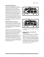
EMS schematic of G424FE LP engine
The SECM makes any necessary corrections to the
air fuel ratio by controlling the inlet fuel pressure to
the air/fuel mixer by modulating the dual fuel trim
valves (FTV) connected to the regulator. Reducing
the fuel pressure leans the air/fuel mixture and
increasing the fuel pressure enriches the air/fuel
mixture. To calculate any necessary corrections to
the air fuel ratio, the SECM uses a number of
different sensors to gain information about the
engine’s performance. Engine speed is monitored
by the SECM through a variable reluctance (VR) or
Hall Effect sensor. Intake manifold air temperature
and absolute pressure are monitored with a TMAP
sensor. MI-07 is a drive-by-wire (DBW) system
connecting the accelerator pedal to the electronic
throttle through the electrical harness; mechanical
cables are not used. A throttle position sensor (TPS)
monitors throttle position in relation to the
accelerator pedal position sensor (APP) command.
Even engine coolant temperature and adequate oil
pressure are monitored by the SECM. The SECM
controller has full adaptive learning capabilities,
allowing it to adapt control function as operating
conditions change. Factors such as ambient
temperature, fuel variations, ignition component
wear, clogged air filter, and other operating
variables are compensated.
MPI (multi-point injection) is used for this system.
Fuel injection pressure and flow rate depend on
engine-specific fuel injection requirements. A variety
of regulators and injectors can be used to fit
individual needs. The gasoline fuel pressure
regulator is a one-way, non-return configuration. All
gasoline specific components are automotive
production parts and validated to strict automotive
standards. Four (4) sequential injection channels
are supported.
Summary of Contents for D20G
Page 2: ......
Page 5: ...Specifications TORQUE SPECIFICATIONS SB2004E00 D e c 1 9 9 8 ...
Page 14: ......
Page 16: ......
Page 138: ...Diesel Engine Engine System 124 NOTE The crankshaft must rotate freely by hand 02900058 ...
Page 254: ......
Page 256: ......
Page 260: ......
Page 341: ...4TNV98 4TNE98 Diesel Engine Section 3 Engine 87 4TNE98 Engine Figure 6 1 ...
Page 423: ...4TNV98 4TNE98 Diesel Engine Section 4 Fuel System 169 Fuel System Components Figure 7 1 ...
Page 477: ...4TNV98 4TNE98 Diesel Engine Section 7 Starter Motor 223 Starter Motor Troubleshooting ...
Page 494: ...4TNV98 4TNE98 Diesel Engine Section 8 Troubleshooting 240 Troubleshooting Charts ...
Page 495: ...4TNV98 4TNE98 Diesel Engine Section 8 Troubleshooting 241 ...
Page 496: ...4TNV98 4TNE98 Diesel Engine Section 8 Troubleshooting 242 ...
Page 498: ...4TNV98 4TNE98 Diesel Engine Section 8 Troubleshooting 244 4TNE98 Engine ...
Page 499: ...Service Manual G424FE LP Engine G424F LP Gasoline Engine G20G G25G G30G SB4320E00 Jan 2008 ...
Page 500: ......
Page 502: ......
Page 529: ...G424F FE Service Manual Chapter 2 Recommended Maintenance 29 ...
Page 534: ...G424F FE Service Manual Chapter 3 Engine Mechanical System 34 MAIN BEARINGS 0 50 UNDERSIZE ...
Page 584: ...G424F FE Service Manual Chapter 3 Engine Mechanical System 84 ...
Page 729: ...G424F FE Service Manual 229 Chapter 8 Basic Troubleshooting ...
Page 731: ...G424F FE Service Manual 231 Chapter 8 Basic Troubleshooting ...
Page 806: ......
Page 808: ......
Page 810: ......
Page 820: ...Power Train System Operation 14 Hydraulic System ...
Page 822: ...Power Train System Operation 16 Hydraulic System ...
Page 824: ...Power Train System Operation 18 Hydraulic System ...
Page 826: ...Power Train System Operation 20 Hydraulic System ...
Page 856: ......
Page 858: ......
Page 860: ......
Page 930: ......
Page 932: ......
Page 934: ......
Page 936: ......
Page 1018: ......
Page 1023: ...A374081 01 ELECTRIC SCHEMATIC MODEL D20 25 30G EM0K2 EM0K3 Cummins B3 3 ...
Page 1024: ...A654030 00 ELECTRIC SCHEMATIC MODEL D20 25 30G EM0QM EM0QN Yanmar 4TNE98 Tier 3 ...
Page 1025: ...A604500 00 ELECTRIC SCHEMATIC MODEL G20 25 30G EM0QF EM0QG GM G424F Non Certi LP ...
Page 1026: ...A604510 00 ELECTRIC SCHEMATIC MODEL G20 25 30G EM0QH EM0QJ GM G424F Non Certi GAS ...
Page 1027: ...A604516 00 ELECTRIC SCHEMATIC MODEL G20 25 30G EM0QY EM0QZ GM G424FE Tier 3 LP ...
Page 1028: ......
Page 1030: ......
Page 1059: ...Safety Section 29 Lean away from the direction of fall Lean forward ...
Page 1071: ...General Section 41 Typical Example Side Shifter Serial Number If Equipped ...


