G424F(FE) Service Manual
Chapter 5. Engine Management System (EMS)
146
Speed Management
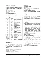
Drive-by-wire refers to the fact that the MI-07 control
system has no throttle cable from the foot pedal to
the throttle body. Instead, the SECM is electronically
connected both to the foot pedal assembly and the
throttle body.
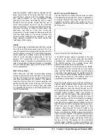
The SECM monitors the foot pedal position and
controls the throttle plate by driving a DC motor
connected to the throttle. The DC motor actuates the
throttle plate to correspond to the foot pedal position
when the operator depresses the pedal. The SECM
will override the pedal command above a maximum
engine speed and below a minimum idle speed.
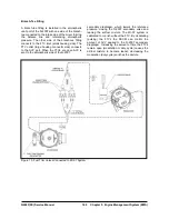
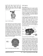
Figure 19. Foot Pedal
The use of electronic throttle control (ETC) ensures
that the engine receives only the correct amount of
throttle opening for any given situation, greatly
improving idle quality and drivability.
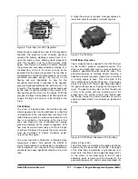
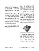
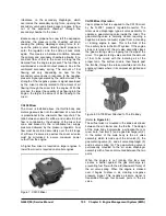
Two throttle position sensors (TPS1 and TPS2),
which are integral to the drive-by-wire (DBW) throttle
assembly, provide feedback for position control by
monitoring the exact position of the throttle valve.
See Figure 20.
SECM self-calibration and “cross checking”
compares both signals and then checks for errors.
Figure 20. Throttle Position Sensor (TPS) on DV-E5
Throttle
NOTE :
The DV-E5 throttle is not a serviceable
assembly. If a TPS sensor fails, the assembly
should be replaced.
The MI-07 system also performs minimum (min) and
maximum (max) speed governing through the
SECM and DBW throttle. For min governing, or idle
speed control, the idle speed is fixed by the SECM.
Unlike a mechanical system, the idle speed is not
adjustable by the end user. The idle speed is
adjusted by the SECM based on engine coolant
temperature. At these low engine speeds, the SECM
uses spark and throttle to maintain a constant speed
regardless of load.
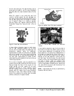
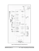
The MI-07 system eliminates the need for air
velocity governors. This substantially increases the
peak torque and power available for a given system
as shown in Figure 21. When the engine speed
reaches the max governing point the speed is
controlled by closing the DBW throttle. Using the
DBW throttle as the primary engine speed control
allows for a smooth transition into and out of the
governor. If excessive over speed is detected, the
engine is shut down.
Figure 21. Peak Torque and Power Available with
MI-07 System
Summary of Contents for D20G
Page 2: ......
Page 5: ...Specifications TORQUE SPECIFICATIONS SB2004E00 D e c 1 9 9 8 ...
Page 14: ......
Page 16: ......
Page 138: ...Diesel Engine Engine System 124 NOTE The crankshaft must rotate freely by hand 02900058 ...
Page 254: ......
Page 256: ......
Page 260: ......
Page 341: ...4TNV98 4TNE98 Diesel Engine Section 3 Engine 87 4TNE98 Engine Figure 6 1 ...
Page 423: ...4TNV98 4TNE98 Diesel Engine Section 4 Fuel System 169 Fuel System Components Figure 7 1 ...
Page 477: ...4TNV98 4TNE98 Diesel Engine Section 7 Starter Motor 223 Starter Motor Troubleshooting ...
Page 494: ...4TNV98 4TNE98 Diesel Engine Section 8 Troubleshooting 240 Troubleshooting Charts ...
Page 495: ...4TNV98 4TNE98 Diesel Engine Section 8 Troubleshooting 241 ...
Page 496: ...4TNV98 4TNE98 Diesel Engine Section 8 Troubleshooting 242 ...
Page 498: ...4TNV98 4TNE98 Diesel Engine Section 8 Troubleshooting 244 4TNE98 Engine ...
Page 499: ...Service Manual G424FE LP Engine G424F LP Gasoline Engine G20G G25G G30G SB4320E00 Jan 2008 ...
Page 500: ......
Page 502: ......
Page 529: ...G424F FE Service Manual Chapter 2 Recommended Maintenance 29 ...
Page 534: ...G424F FE Service Manual Chapter 3 Engine Mechanical System 34 MAIN BEARINGS 0 50 UNDERSIZE ...
Page 584: ...G424F FE Service Manual Chapter 3 Engine Mechanical System 84 ...
Page 729: ...G424F FE Service Manual 229 Chapter 8 Basic Troubleshooting ...
Page 731: ...G424F FE Service Manual 231 Chapter 8 Basic Troubleshooting ...
Page 806: ......
Page 808: ......
Page 810: ......
Page 820: ...Power Train System Operation 14 Hydraulic System ...
Page 822: ...Power Train System Operation 16 Hydraulic System ...
Page 824: ...Power Train System Operation 18 Hydraulic System ...
Page 826: ...Power Train System Operation 20 Hydraulic System ...
Page 856: ......
Page 858: ......
Page 860: ......
Page 930: ......
Page 932: ......
Page 934: ......
Page 936: ......
Page 1018: ......
Page 1023: ...A374081 01 ELECTRIC SCHEMATIC MODEL D20 25 30G EM0K2 EM0K3 Cummins B3 3 ...
Page 1024: ...A654030 00 ELECTRIC SCHEMATIC MODEL D20 25 30G EM0QM EM0QN Yanmar 4TNE98 Tier 3 ...
Page 1025: ...A604500 00 ELECTRIC SCHEMATIC MODEL G20 25 30G EM0QF EM0QG GM G424F Non Certi LP ...
Page 1026: ...A604510 00 ELECTRIC SCHEMATIC MODEL G20 25 30G EM0QH EM0QJ GM G424F Non Certi GAS ...
Page 1027: ...A604516 00 ELECTRIC SCHEMATIC MODEL G20 25 30G EM0QY EM0QZ GM G424FE Tier 3 LP ...
Page 1028: ......
Page 1030: ......
Page 1059: ...Safety Section 29 Lean away from the direction of fall Lean forward ...
Page 1071: ...General Section 41 Typical Example Side Shifter Serial Number If Equipped ...


