OPERATOR’S MANUAL
Control Point
®
11001-1489-201702 Rev B
TROUBLESHOOTING / 87
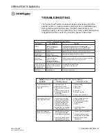
TROUBLESHOOTING
The Control Point
®
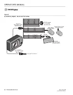
system contains six basic components, each with a
specific function. Component failures normally react in predictable ways,
making fault isolation relatively easy. If certain components are not
operating properly, such as a hydraulic pump or motor, system performance
is degraded and the console may incorrectly appear to be at fault.
Tab
le 1. Component Interconnections
Component
Connected To
Function
Console
12VDC vehicle battery
Compares vehicle ground speed to conveyor/auger
and all components of
and liquid pump speeds and controls the hydraulic valves
control system.
(or DC motor for liquid) for the desired application rates.
Switch Module
Console
Provides operator controls for system real-time functions.
Vehicle Ground
Mechanical or
Indicates vehicle ground speed to console.
Speed Sensor
electronic speedometer.
Sensors for
Conveyor/auger and
Indicate conveyor/auger speed, spinner speed, and liquid flow
Application Rate
spinner or related
and Spinner Speed rate or pressure to Console.
hydraulic motor shafts,
plumbing after liquid pump.
Actuators for Servo
Conveyor/auger and spinner
Regulate conveyor/auger speed,
or Proportional Valves
hydraulic control valves and
spinner speed, and liquid flow
and Liquid Pump
liquid pump.
rate.
Harnesses
All components
Connect all components.
Table 2.
Common Spreader Problems (Control System Normal)
Symptom
Probable Cause
Corrective Action
Conveyor/auger does not
1. Hydraulic pump off.
1. Engage pump.
run in either AUTO or
2. Manual valve closed.
2. Open valve.
UNLOAD
3. Hydraulic quick-connector
3. Reconnect.
loose.
4. Conveyor/auger jammed
4. Clear jam.
5. Relief valve operating at
5. Adjust or replace.
low pressure.
6. Loss of hydraulic oil.
6. Repair leak and refill oil.
Convey/auger does not
1. Faulty hydraulic system.
1. Repair hydraulic system.
reach maximum speed
2. Conveyor/auger binding.
2. Eliminate binding.
3. Relief valve defective or
3. Adjust to proper pressure
set lower than specified.
or replace valve.
4. Material lumping and
4. Clear.
jamming conveyor/auger.
5. Engine RPM low because
5. Shift to lower gear
using wrong gear or axle.
and/or axle.
Inaccurate application
1. Material density changed
1. Repeat Granular Calibration.
(APR error exceeds 10%)
from original calibration.
2. Feed-gate setting changed.
2. Set gate to position used
during Granular Calibration.
3. Inaccurate ground speed
3. Repeat Ground Speed
input because tire size or
Calibration.
axle ratio has been changed.
Summary of Contents for Control Point
Page 1: ...CONTROL POINT CONTROL SYSTEM Operator s Manual SINCE 1966 ...
Page 5: ...OPERATOR S MANUAL Control Point 11001 1489 201702 Rev B IV ...
Page 7: ...OPERATOR S MANUAL Control Point 11001 1489 201702 Rev B 2 SAFETY NOTICES ...
Page 13: ...OPERATOR S MANUAL Control Point 11001 1489 201702 Rev B 8 INTRODUCTION ...
Page 29: ...OPERATOR S MANUAL Control Point 11001 1489 201702 Rev B 24 START UP AND FAMILIARIZATION ...
Page 77: ...OPERATOR S MANUAL Control Point 11001 1489 201702 Rev B 72 KEYBOARD PROGRAMMING ...
Page 79: ...OPERATOR S MANUAL Control Point 11001 1489 201702 Rev B 74 SYSTEM CALIBRATION ...
Page 91: ...OPERATOR S MANUAL Control Point 11001 1489 201702 Rev B 86 SYSTEM CALIBRATION ...


