OPERATOR’S MANUAL
Control Point
®
11001-1489-201702 Rev B
92 / TROUBLESHOOTING
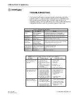
SYSTEM DOES NOT OPERATE
Probable Cause
If the system does not respond with the Master switch in Auto or Unload or
the Blast button has not effect, the hydraulic valve may not be opening to
supply hydraulic oil to the conveyor motor (spreader system) or the pump
may not be rotating to supply liquid to the spray bar (liquid system).
Corrective Action
The following four steps describe repair for a pulse width modulated
hydraulic valve (Rexroth, Gresen, Vickers, Parker, etc.). Begin by
disconnecting the electrical connections at the solenoid coil and then set
the MASTER Switch into UNLOAD position to prevent possible damage to
the PWM valve driver and coil.
1. Check voltage readings on the granular valve connector of the main
harness at pin 16 and 8. Use pin 15 as ground. Pin 16 should read
battery voltage (+12V); pin 8 reads a percentage of +12V determined
by PWM SAT value entered under Granular Configuration (F3). (i.e. If
PWM SAT is 40, then a reading of +4.8 V. –12 x .40 = 4.8 be present).
2. Check voltage readings at the solenoid valve coil. The WHT wire
supplies the PWM voltage signal to the coil; the GRY wire is signal
ground. Voltage reading should be equal to reading in step above. If
voltages are not present, check wiring harnesses for cuts or shorts.
3. If voltages are present a hydraulic valve or hydraulic flow problem is
indicated.
4. If the above checks are normal, replace the PWM valve driver. If this
does not the solve problem, replace the console.
Corrective Action for Granular Channel
Begin by disconnecting the electrical connections at the solenoid coil. Then
set the MASTER switch to the UNLOAD position for the following two steps
to prevent possible actuator damage.
1. Check voltage readings on the granular valve connector of the main
harness at pins 16 and 8. Use pin 15 as ground. Pin 16 and 8 should
read battery voltage (+12V).
2. If voltages are present and actuator does not rotate, replace the
actuator.
3. If voltages are not present replace main harness, valve extension
cable, or console.
Corrective Action for a Sprayer Channel
If the sprayer system is not spraying, begin by disconnecting the electrical
connections at the pump or solenoid coil. Then switch the MASTER switch
to the UNLOAD position for the following checks to prevent possible
damage to the liquid valve driver and coil.
1. Check voltage reading on the RED and BRN wires at the liquid valve
connector of the main harness. Use the BLK wire as ground.
Summary of Contents for Control Point
Page 1: ...CONTROL POINT CONTROL SYSTEM Operator s Manual SINCE 1966 ...
Page 5: ...OPERATOR S MANUAL Control Point 11001 1489 201702 Rev B IV ...
Page 7: ...OPERATOR S MANUAL Control Point 11001 1489 201702 Rev B 2 SAFETY NOTICES ...
Page 13: ...OPERATOR S MANUAL Control Point 11001 1489 201702 Rev B 8 INTRODUCTION ...
Page 29: ...OPERATOR S MANUAL Control Point 11001 1489 201702 Rev B 24 START UP AND FAMILIARIZATION ...
Page 77: ...OPERATOR S MANUAL Control Point 11001 1489 201702 Rev B 72 KEYBOARD PROGRAMMING ...
Page 79: ...OPERATOR S MANUAL Control Point 11001 1489 201702 Rev B 74 SYSTEM CALIBRATION ...
Page 91: ...OPERATOR S MANUAL Control Point 11001 1489 201702 Rev B 86 SYSTEM CALIBRATION ...

