


OPERATOR’S MANUAL
Control Point
®
11001-1489-201702 Rev B
KEYBOARD PROGRAMMING / 55
BOOM CONFIGURATION
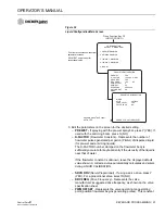
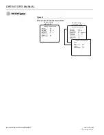
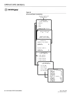
7. Press the F5 Function Key to return to Liquid Configuration screen.
Select the 5 key to display the Boom Configuration screen.
Figure 36
Liquid Channel Boom Sections Configuration
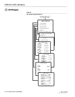
8. Select a Boom Section and press a number key for the desired
SECTION CONFIGURATION screen (refer to Figure 36).
CONFIGURATION
SELECT A MENU ITEM
1 LIQUID 1 ENABLED
2 LIQUID 2 DISABLED
3 LIQUID 3 DISABLED
4 LIQUID 4 DISABLED
5 BOOM
Press Function Key F5
(LIQUID CONFIG)
BOOM CONFIGURATION
SELECT A MENU ITEM
1 SECTION 1
2 SECTION 2
3 SECTION 3
4 SECTION 4/PAUSE
5 SECTION 5 / AUTO ANTI-ICING
SECTION 1 CONFIGURATION
SECTN ENBLED
YES
12V ON
NO
NUM OF NZZLS
1
NZZLE SPCNG
36.0 IN
BOOM INPUT
YES
SECTION 4 CONFIGURATION
SECTN ENBLED
YES
12V ON
NO
BOOM INPUT
NO
PAUSE ENABLE
NO
• Section 5 adds BOOM INPUT
selection.
SECTION 5 CONFIGURATION
12V ON
NO
BOOM INPUT
NO
Summary of Contents for Control Point
Page 1: ...CONTROL POINT CONTROL SYSTEM Operator s Manual SINCE 1966 ...
Page 5: ...OPERATOR S MANUAL Control Point 11001 1489 201702 Rev B IV ...
Page 7: ...OPERATOR S MANUAL Control Point 11001 1489 201702 Rev B 2 SAFETY NOTICES ...
Page 13: ...OPERATOR S MANUAL Control Point 11001 1489 201702 Rev B 8 INTRODUCTION ...
Page 29: ...OPERATOR S MANUAL Control Point 11001 1489 201702 Rev B 24 START UP AND FAMILIARIZATION ...
Page 77: ...OPERATOR S MANUAL Control Point 11001 1489 201702 Rev B 72 KEYBOARD PROGRAMMING ...
Page 79: ...OPERATOR S MANUAL Control Point 11001 1489 201702 Rev B 74 SYSTEM CALIBRATION ...
Page 91: ...OPERATOR S MANUAL Control Point 11001 1489 201702 Rev B 86 SYSTEM CALIBRATION ...


