


OPERATOR’S MANUAL
Control Point
®
11001-1489-201702 Rev B
18 / START-UP AND FAMILIARIZATION
switch is held, the value repeats until reaching a preset limit. If
changed while the vehicle is moving, the new target APR displays for
approximately two seconds, then reverts to the actual APRs.
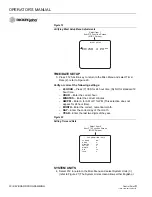
Figure 10
Operate Screen Showing Product Application
3. Rotating the width adjust knob on the
Switch Module changes the
rotational speed of the spinner and will show the percentage on the
Spread Width Bar of the display
.
The horizontal bar graphically
represents the position of the Spread Width knob. The bar is at the
100% position when the knob is fully clockwise corresponding to
maximum spinner speed. The operator determines the correct setting
by observing the spread pattern. The bar is hollow until the spinner is
operating.
4. Date and time appears at screen bottom.
5. All boom sections appear as rectangle blocks during anti-ice operation
with each section hollow until activated.
6. Alarm messages will flash in the middle of the screen above the
Spread Width bar (Refer to Figure 10).
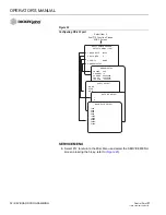
MATERIAL/MANUAL SPEED SELECT
NOTE: The Material Selection screen
limits the display of prewet and
anti-ice materials to only the
active type when the Boom 5
input is configured for prewet/
anti-ice selection. (If materials 1
and 2 are prewet and 3 and 4
are anti-ice, and the Boom 5
switch is in prewet mode; only
material 1 and 2 will appear.
Changing the Boom 5 switch to
anti-ice, only materials 3 and 4
will display.
This screen is divided into two major divisions. The upper portion of the
screen is Material Select indicating products programmed for use. The
lower portion is the Manual Speed display that allows selection of an
artificial ground speed signal in the event the standard ground speed sensor
fails. Without a ground speed signal, the system is inoperative unless
manual speed operation is selected.
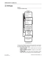
This screen can only be accessed if:
1. The vehicle is stationary (zero ground speed)
2. The Master Switch is in the OFF position
3. Manual ground speed has been enabled during programming.
4. More than 1 granular and 1 liquid material has been enabled.
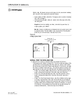
SALT LIQUID 1
MPH
50
LBS / MILE GAL / TON
SPREAD WIDTH 100%
9 : 15 AM
495 4.9
0%
26 AUG 06
Ground speed window
indicates actual rate of travel
0
Spread Width Bar
Indicates Spread Width
switch setting of 40%
Granular and Liquid Channels
Large size values
indicate application
of product is being applied
APPLICATION RATE ERROR
LIQUID 1
Error Message
Window
Lists error type
and location of error
Summary of Contents for Control Point
Page 1: ...CONTROL POINT CONTROL SYSTEM Operator s Manual SINCE 1966 ...
Page 5: ...OPERATOR S MANUAL Control Point 11001 1489 201702 Rev B IV ...
Page 7: ...OPERATOR S MANUAL Control Point 11001 1489 201702 Rev B 2 SAFETY NOTICES ...
Page 13: ...OPERATOR S MANUAL Control Point 11001 1489 201702 Rev B 8 INTRODUCTION ...
Page 29: ...OPERATOR S MANUAL Control Point 11001 1489 201702 Rev B 24 START UP AND FAMILIARIZATION ...
Page 77: ...OPERATOR S MANUAL Control Point 11001 1489 201702 Rev B 72 KEYBOARD PROGRAMMING ...
Page 79: ...OPERATOR S MANUAL Control Point 11001 1489 201702 Rev B 74 SYSTEM CALIBRATION ...
Page 91: ...OPERATOR S MANUAL Control Point 11001 1489 201702 Rev B 86 SYSTEM CALIBRATION ...


