


OPERATOR’S MANUAL
Control Point
®
11001-1489-201702 Rev B
KEYBOARD PROGRAMMING / 39
AIR TEMPERATURE SENSOR
Select F12 to return to the Misc Menu and select the MORE MENU screen
pressing the 3 key.
The Air Temperature Sensor monitors air temperature changes. Three
temperature alarm settings can be programmed. The Air Temperature
Sensor connects to the Temperature Sensor Adapter (466492100S1). The
Temperature Sensor Adapter connects to the main harness on the lead
labeled Temperature. For earlier versions of Control Point
®
harnesses, the
adapter connects to the mating connector in the adapter harness
(466492040S1).
When enabled, the Air Temperature will replace the date in the lower left
side of the Operate screen.
CONFIGURATION
Air Temperature default is set for no temperature sensors. To change
configurations, press Y (Yes) or N (No).
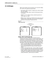
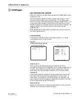
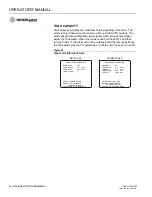
Figure 27
Air Temperature Sensor Screens
Alarm Temp 1-3
There are three user-definable temperature alarms to alert of air
temperature changes and that application rate or material changes may be
required. The temperatures must be entered in descending order with
Alarm Temp 1 the highest setting and Alarm Temp 3 the lowest setting.
Temp Hyst+
Temperature Hysteresis indicates the positive temperature changes that
has to occur above the active alarm temperature to clear the alarm. If
Alarm Temp 1 is 20 degrees F and the Temp Hyst+ is 5 degrees F, the
alarm activates when the temperature drops below 20 degree F but clears
when the temperature reaches 25 degrees F.
High & Low Cal
High & Low Cal values are created from the calibration routine and are for
reference only. These values cannot be altered.
AIR TEMPERATURE SENSOR
TEMP SNSR
NO
AIR TEMPERATURE SENSOR
TEMP SNSR
YES
ALRM TEMP1
32.0 F
ALRM TEMP2
20.0 F
ALRM TEMP3
10.0 F
TEMP HYST+
5.0
F
HIGH CAL
2.7
VOLT
LOW CAL
0.76 VOLT
PRESS C TO CALIBRATE
No Temperature Sensor
Air Temperature Sensor
Summary of Contents for Control Point
Page 1: ...CONTROL POINT CONTROL SYSTEM Operator s Manual SINCE 1966 ...
Page 5: ...OPERATOR S MANUAL Control Point 11001 1489 201702 Rev B IV ...
Page 7: ...OPERATOR S MANUAL Control Point 11001 1489 201702 Rev B 2 SAFETY NOTICES ...
Page 13: ...OPERATOR S MANUAL Control Point 11001 1489 201702 Rev B 8 INTRODUCTION ...
Page 29: ...OPERATOR S MANUAL Control Point 11001 1489 201702 Rev B 24 START UP AND FAMILIARIZATION ...
Page 77: ...OPERATOR S MANUAL Control Point 11001 1489 201702 Rev B 72 KEYBOARD PROGRAMMING ...
Page 79: ...OPERATOR S MANUAL Control Point 11001 1489 201702 Rev B 74 SYSTEM CALIBRATION ...
Page 91: ...OPERATOR S MANUAL Control Point 11001 1489 201702 Rev B 86 SYSTEM CALIBRATION ...


