background image

OPERATOR’S MANUAL

Control Point

®

11001-1489-201702 Rev B

74 / SYSTEM CALIBRATION

Summary of Contents for Control Point

Page 1: ...CONTROL POINT CONTROL SYSTEM Operator s Manual SINCE 1966 ...

Page 2: ...racket Mounting 10 Console and Switch Module Installation 10 Switch Module to Console Connection 11 Console Mounting 11 Harness Connection 11 Main Harness Connection 12 Checking Operation 13 Start up and Familiarization 15 Start up Preparation 15 Start up Procedure 15 Operate Screen Display Functions 17 Material Manual Speed Select 18 Accessing the Current Totals Screen 20 Clearing the Current Tot...

Page 3: ... 52 Enabling Tank Level Sensor 53 Tank Empty and Tank Full 53 Tank Alarm 53 Tank Capacity 54 Boom Configuration 55 Programming Liquid Application Rates F4 57 Ground Speed Configuration F7 61 Ground Speed Calibration F7 1 63 Spinner Channel Configuration F8 65 Monitor Reset Accumulators F9 67 Reading System Information F10 69 Performing System Response F11 71 System Calibration 73 Recording Calibra...

Page 4: ...OPERATOR S MANUAL Control Point 11001 1489 201702 Rev B III Appendix A Converting Constants 97 Fine Tuning Application 97 Calculating Spreader Constants 98 Calibration Data Record Sheet 99 Warranty 107 ...

Page 5: ...OPERATOR S MANUAL Control Point 11001 1489 201702 Rev B IV ...

Page 6: ...ous situation which if not avoided could result in death or serious injury Use of the word CAUTION with the Safety Alert Symbol indicates a potentially hazardous situation which if not avoided may result in minor or moderate injury Use of the word CAUTION without the safety alert symbol indicates a potentially hazardous situation which if not avoided may result in equipment damage DISCLAIMER DICKE...

Page 7: ...OPERATOR S MANUAL Control Point 11001 1489 201702 Rev B 2 SAFETY NOTICES ...

Page 8: ... APR application rate coverage for bridges and intersections with a much heavier amount of material Figure 1 illustrates the Console Switch Module and Keyboard Figure 1 System Components GRANULAR CHANNEL CONFIGURATION The granular channel controls the amount of material dumped onto the spinner plate s The Control Point monitors a tachometer style feedback sensor located on the V box drag chain or ...

Page 9: ...dule The user must determine the spread width accuracy needed Technical assistance is available through DICKEY john Technical Support at PH 1 800 637 2952 PRODUCT APPLICATION MECHANISMS The granular and spinner channels use in addition to feedback shaft rotation sensors proportional valves to control the product application and spinner speed The liquid channel uses in addition to feedback sensors ...

Page 10: ...ioned elsewhere for operator convenience Figure 2 System Block Diagram CONSOLE The Console displays information on a dot matrix LCD and uses a single push button switch to control system power and to view several operator screens Using an external keyboard for programming and placing operator controls on the Switch Module simplifies the Console CONSOLE Store User Entered and Accumulated Data Trans...

Page 11: ...ess The Wireless Switch Module is similar to the Standard however it provides for data transfer to a PC via a wireless transmission to a base station KEYBOARD The keyboard is used to program and calibrate the system The 86 key alphanumeric PC compatible keyboard has been environmentally hardened for use in the ice control field After programming and calibration are finished the keyboard is usually...

Page 12: ...the warning alarm area of the Operate screen HARNESSES Main Harness Assembly Connects the Console to the ground speed sensor feedback sensors channel valve or DC motor actuators vehicle battery ignition and additional optional connections including two speed axle hopper level sensor and boom sense inputs Retro Harness Assembly Connects a Control Point console to an ICS2000 harness refer to Figure ...

Page 13: ...OPERATOR S MANUAL Control Point 11001 1489 201702 Rev B 8 INTRODUCTION ...

Page 14: ...ns are made to the sensor and actuator cables battery ignition switch and additional options two speed axle hopper level sensor and boom sense inputs as required Verify all items in the appropriate hardware mounting kit are present HARDWARE KITS STANDARD HARDWARE KIT 46649 0380 FOR CONSOLE AND SWITCH MODULE 1 Combination mounting plate 46649 0580 2 U bracket 46649 0590 3 Two 1 4 20 x 1 inch hex bo...

Page 15: ...re wiring and other obstructions located beneath the dash 2 Drill two 9 32 inch holes 3 Position the U bracket in place on the mounting surface and insert the two 1 inch bolts 4 Install the lock washers and nuts and tighten them CONSOLE AND SWITCH MODULE INSTALLATION 1 Install the Console onto the mounting plate using three 3 4 inch bolts and lock washers 2 When using the combination mounting plat...

Page 16: ...the two knob screws The rubber washers fit between the U bracket and the mounting plate tabs 2 Pivot the Console for the best viewing angle and tighten the two knob screws HARNESS CONNECTION 1 Verify all required exterior system cables are installed on the spreader vehicle according to their separate individual instructions These are defined as the sensor actuator ground speed boom sense and hoppe...

Page 17: ...ole Anchor all cables suitable with nylon cable ties to prevent damage due to flexing and scraping RTV or silicone caulk can be used to seal the hole Do not connect the RED ignition lead directly to the battery voltage This will prevent the system from storing data properly 3 Connect the RED ignition lead to the switched terminal of the ignition switch The correct terminal is at 12 volts DC or hig...

Page 18: ... the OPERATE screen refer to Figure 9 2 Refer to the Startup and Familiarization section for additional testing Figure 4 Switch Module Cabling 435 SALT LBS MILE LIQUID GAL TON MPH 0 100 SPREAD WIDTH 8 MAR 12 25 PM 1 2 3 4 5 6 7 8 9 0 Q W E R T Y U I O P A S D F G H J K L Back Space Z X C V B N M RS232 Connector for Computer Display Console Keyboard Connectors Switch Module Keyboard Connects to Rea...

Page 19: ...r Hopper Level Sensor Battery Ð Boom Sensors Flowmeter Tank Level or Down Pressure Granular Application Rate Sensor Spinner Sensor Liquid Valve Granular Spinner 2 Speed Axle Ignition Alternate sets of connectors Insulate and tie back unused connectors CPC connector Main Harness 12V Relay Gate Height Sensor Road Watch Adapter ...

Page 20: ... calibrated before performing the following procedures IMPORTANT Practice the following procedures with the vehicle stationary to gain familiarity with the operating controls and screens before applying product Figure 6 Switch Module Controls START UP PROCEDURE 1 Verify the Switch Module Master Switch is in the OFF position as shown in Figure 6 If the Master Switch is in the AUTO position during O...

Page 21: ...ld until unit powered OFF before the truck was turned OFF 4 Briefly press the Console button less than a second to apply power to the Console refer to Figure 8 If the button is held too long the Operate screen is skipped a beep will sound and the Accessory screen appears instead If this occurs continue pressing the Console button until the Operate screen appears or turn the console off and on agai...

Page 22: ...l is not active Ground speed is independent of product application and therefore displays only when the vehicle is moving Product application begins with vehicle motion if the Master Switch is in the AUTO position The actual APRs display almost twice the size of the target APRs refer to Figure 7 2 The target rate of either product channel can be changed by pressing the respective INC DEC switch on...

Page 23: ... prewet and anti ice materials to only the active type when the Boom 5 input is configured for prewet anti ice selection If materials 1 and 2 are prewet and 3 and 4 are anti ice and the Boom 5 switch is in prewet mode only material 1 and 2 will appear Changing the Boom 5 switch to anti ice only materials 3 and 4 will display This screen is divided into two major divisions The upper portion of the ...

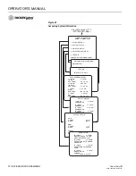
Page 24: ...ter up or down on the left side of either list NOTE Figure 11 If a switch module with wireless communication capability is connected a download screen will display Figure 11 Operator Screens Available by Cycling SALT LIQUID 1 MPH 0 LBS MILE GAL TON SPREAD WIDTH 100 9 15 AM 500 5 0 0 26 AUG 97 CURRENT TOTALS SALT TONS AUTO 112 0 MILES AUTO 823 0 HOURS AUTO 26 10 TONS BLAST 7 3 MILES BLAST 68 4 HOUR...

Page 25: ... a speed that has been programmed 3 Continue spreading material maintaining displayed speed as closely as possible to ensure accurate application The system spreads material but no accumulators are updated since system accuracy cannot be assured The related sensor and harness should be inspected and repaired as soon as possible to restore normal operation Returning to the Operate Screen 1 To cycle...

Page 26: ... the totals reset to zero as shown in Figure 13 To clear the bottom half repeat the steps for the liquid channel with the Liquid right switch refer to Figure 14 Press the console button to stop the clear operation Figure 13 Clearing Top Half of Current Totals Screen CURRENT TOTALS SALT TONS AUTO 112 0 MILES AUTO 823 0 HOURS AUTO 26 10 TONS BLAST 7 3 MILES BLAST 68 4 HOURS BLAST 1 55 LIQUID 1 GAL A...

Page 27: ...ogrammed rate The BLAST button performs several functions depending upon programming options 1 With the Operate screen displaying press the Blast button on the side of the Switch Module When the Blast button is pressed the Operate screen displays BLAST ON above the Spread Width bar Thiseither initiates a timed blast cycle programmed length or momentary blasts CURRENT TOTALS PRESS DEC TO CONFIRM CL...

Page 28: ...of the master switch is used to quickly remove material from the truck There must be no ground speed for the Unload function to operate If ground speed is dedicated the Unload feature will not work If the spinner is programmed to operate during UNLOAD be sure that no one is in the vicinity before performing this procedure to avoid possible injury 1 Back up to the appropriate location and momentari...

Page 29: ...OPERATOR S MANUAL Control Point 11001 1489 201702 Rev B 24 START UP AND FAMILIARIZATION ...

Page 30: ...m calibration constants are determined through regular calibration routines However known constants at the time of programming can be entered reducing the calibration procedures required Calibration corrections can be revised anytime to fine tune accuracy LOGGING CONFIGURATION DATA In the event of Console damage lost data upgrading software or replacement all calibration constants and other system...

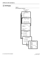
Page 31: ...other function can be done by pressing another F key 4 Basic screen layout includes Function screen top level Each screen lists items with numbers to the left side except F8 Pressing the indicated key number displays that screen usually one with parameters for editing Parameter screens second level An index arrow appears to the left of the first item and an underscore beneath the first digit of th...

Page 32: ...the previous screen Pressing any function key F1 through F12 transfers directly to that function Screen prompts If MORE appears on a screen additional parameters are on an extended screen Access this screen by moving the index arrow to the MORE line refer to Figure 18 MISCELLANEOUS MENU SELECT A MENU ITEM 1 BLAST SETUP 2 TIME DATE 3 SYSTEM UNITS 4 SERIAL PORT CONFIGURATION 5 CHANGE LANGUAGE 6 SERV...

Page 33: ... 201702 Rev B 28 KEYBOARD PROGRAMMING 5 All programming steps should be performed in the order outlined in this manual to ensure proper entries for all parameters The master switch must be OFF before functions can be selected with the keyboard ...

Page 34: ...gth of the BLAST cycle 0 to 99 seconds When set to zero 0 the blast cycle lasts only as long as the BLAST button is pressed BLAST SPEED Establishes an artificial vehicle ground speed when vehicle is at a standstill or moving slow that computes the rate material dispenses during blasting For speeds faster than this value the actual vehicle ground speed determines the spread rate If Blast is set to ...

Page 35: ... PM Enter A for AM or P for PM This selection does not appear for 24 hour time MONTH Enter the correct numerical month DAY Enter the correct day of the month YEAR Enter the last two digits of the year Figure 20 Setting Time and Date SYSTEM UNITS 4 Select F12 to return to the Misc Menu and select System Units 3 refer to Figure 21 The System Units screen allows either English or BLAST SETUP BLAST TI...

Page 36: ...lues must match the serial data format of the other serial devices The Esc key accepts the values instead of the Enter key The pre programmed values are appropriate for use with other DICKEY john equipment and software Press 1 for the Baud Rate Select screen Use the Up Down arrow keys to change the baud rate Press Esc key when finished Press 2 for the Data Bit Select screen Use the Up Down arrow k...

Page 37: ... screen pressing the 5 key refer to Figure 23 RS232 CONFIGURATION SELECT A MENU ITEM 1 BAUD RATE 19200 2 DATA BITS 8 3 PARITY NONE 4 MODEM SETUP Select Item 4 from F12 Function Screen MISC Screen MODEM SETUP ENABLE YES CHANNEL 15 PC ADDR 4D00264D TRUCK 4004D26F TRUCK ID 110011391 PARITY SELECT NONE EVEN ODD DATA BIT SELECT 7 8 BAUD RATE SELECT 1200 2400 4800 9600 14400 19200 28800 38400 57600 ...

Page 38: ...ngs SERVICE MENU SELECT A MENU ITEM 1 UPDATE SOFTWARE 2 DISPLAY SOFTWARE VERSION 3 SYSTEM RESET 4 SYS RESPONS 5 CHANGE LANGUAGE KEYBOARD F12 Function Screen MISC Menu CHANGE LANGUAGE KEYBOARD FRENCH LANGUAGE NO FRENCH KEYBOARD NO SYS RSPNS SELECT A MENU ITEM 1 GRANULAR 2 LIQUID PRE WET 3 LIQUID ANTI ICING 4 SPINNER SYSTEM RESET DO YOU REALLY WANT TO CLEAR ALL STORED VALUES AND RETURN TO FACTORY DE...

Page 39: ...s useful for troubleshooting This screen can be viewed but not changed CHANGE LANGUAGE KEYBOARD Select a language and keyboard from the screen The system displays English and one other language usually French Canadian Contact DICKEY john for available alternative languages Select KEYBOARD from the screen N NO selects an English keyboard Y YES selects French ...

Page 40: ...E DATE 3 SYSTEM UNITS 4 SERIAL PORT CONFIGURATION 5 SERVICE MENU 6 MORE MISCELLANEOUS MENU SELECT A MENU ITEM 1 GATE HEIGHT SENSOR 2 ROAD TEMPERATURE SENSOR 3 AIR TEMPERATURE SENSOR 4 12V BOOM SWITCHED OUTPUT 5 DOWN PRESSURE SENSOR 6 BED HEIGHT SENSOR Select Item 6 from F12 Function Screen MISC Menu BED HEIGHT SENSOR ENABLED NO DOWN PRESSURE SENSOR ENABLED NO 12V BOOM SWITCHED OUTPUT ENABLED NO AI...

Page 41: ...re 25 Gate Height Screens GATE HEIGHT CALIBRATION There are seven user definable Gate Heights to enter that will aid in Gate Height calibration Enter seven Gate Height settings that will be used when spreading material Calibration Steps 1 From the Gate Height Sensor screen position the arrow at the Closed position 2 Set the Gate to Closed 3 Measure the height at the Closed position and enter the G...

Page 42: ...bled and has been calibrated all of the desired granular materials that are enabled must be re calibrated through a material drop test Refer to Calibrating Granular Materials section If enabled materials are not calibrated the Control Point will alarm ROAD TEMPERATURE SENSOR Select F12 to return to the Misc Menu and select the MORE MENU screen pressing the 2 key The Road Temperature Sensor monitor...

Page 43: ... calibration routine and are for reference only and cannot be edited NOTE Road Watch is a registered trademark of Commercial Vehicle Group Surface Patrol technology is a registered trademark of Control Products Inc TEMPERATURE SENSOR CALIBRATION Press C to start the Temperature Sensor Adapter automatic calibration procedure Calibration lasts approximately 10 20 seconds Calibration is complete when...

Page 44: ...27 Air Temperature Sensor Screens Alarm Temp 1 3 There are three user definable temperature alarms to alert of air temperature changes and that application rate or material changes may be required The temperatures must be entered in descending order with Alarm Temp 1 the highest setting and Alarm Temp 3 the lowest setting Temp Hyst Temperature Hysteresis indicates the positive temperature changes ...

Page 45: ...n lasts approximately 10 20 seconds Calibration is complete when the Air Temperature Sensor menu displays IMPORTANT The RoadWatch temperature sensor or Surface Patrol temperature sensor must be disconnected and the Temperature Sensor Adapter connected to the main harness for successful calibration If the Temperature Sensor Adapter is disconnected when calibration is performed an error screen will ...

Page 46: ... Screens The 12V Boom Switched Output functionality varies for different versions of the hardware console To Verify Software Version Press Miscellaneous F12 Service Menu 5 Display Software Version 2 Any consoles with no hardware version number indicated or the version is found in a different location than described above is also a Version 1 software Hardware Version 1 consoles require the followin...

Page 47: ...o become active When enabled a bar graph with a digital percentage readout representing the down pressure displays When the Down Pressure sensor is enabled the tank level is automatically disabled If granular is enabled the spinner bar graph and the down pressure bar graph share its portion of the Operate screen NOTE The Tank Level Sensor and the Down Pressure Sensor cannot be configured or used a...

Page 48: ...r on a regularly scheduled interval to insure proper operation of the bed height alarm Visual inspection of the bed height must be maintained as the primary indicator of safe bed height operation The alarm should only be used as a secondary convenience indicator The operator assumes all risk in using this feature DICKEY john assumes no responsibility for alarm failure to indicate an unsafe operati...

Page 49: ...automatic entry Select the Bed Down text and press C to capture the sensor voltage Bed Alarm indicates the voltage when the bed has exceeded normal operating height and can be entered manually or automatically captured Manual Entry Select the Bed Alarm text and enter the voltage when the bed exceeds the normal operating height Automatic Entry The dump bed must be near the maximum operating height ...

Page 50: ...e Accumulator Function F9 These totals are those products selected on the Material Manual Speed Select Screen To see other totals select those products from that screen SEASON TOTALS screen Shows the amount of material applied miles traveled during application and hours elapsed this season for each product in both the AUTO and BLAST modes The season totals can only be cleared from the Accumulator ...

Page 51: ... GT HGT Calibration Gate Height Displayed only if optional Gate Height Sensor is Enabled If Enabled the Calibration Gate Height valve displayed is the setting of the gate height in inches when the spreader was calibrated Refer to page 77 for the Spreader Calibration procedure Changing the original calibrated gate setting by adjusting the conveyor speed provides a more accurate granular material ap...

Page 52: ...is not displayed when SRVO DRV is set to YES SYS RSPNS System Response Adjusts the control system response time to the hydraulic and mechanical systems of the granular control channel on each particular spreader vehicle VALV BOOST Valve Boost Increases the amount of system response initially applied to the granular control to reach final operating speed as quickly as possible AFILT A Filter Filter...

Page 53: ...r NO disabled At least one granular material must be enabled unless console is used for anti icing then all granulars can be disabled All products can be programmed and calibrated now and selected from the Operate mode later STEP METHD Y YES selects the Step method or N NO the Rate method to specify application rates APRs Since each method performs essentially the same function the choice becomes ...

Page 54: ...button is pressed CHNL LBL Channel Label Step or Rate method Any product material name of up to nine 9 characters can be keyed in Pressing the ENTER key stores the name for display on all granular screens including the OPERATE screen wherever that material appears in the event there is a data download 4 Press F2 to return to the GRANULAR APPL RATE screen If other granular materials require program...

Page 55: ...nction key F5 to obtain the LIQUID CONFIG screen refer to Figure 34 Four 4 liquid material names appear with the option to ENABLE or DISABLE Products are enabled disabled from the LIQUID APPL RATE screen F4 SETTING LIQUID CONFIGURATIONS 2 Select a material using the corresponding number key APPLICATION RATE SELECT A MENU ITEM 1 SALT ENABLED 2 SAND DISABLED 3 MIX A DISABLED 4 MIX B DISABLED Press F...

Page 56: ... enters during LIQUID CALIBRATION SRVO DRV Servo Proportional If using a servo drive press Y YES For a proportional valve select N NO DRV FREQ Drive Frequency Represents the valve manufacturer s suggested drive frequency as shown on the valve specification sheet PWM OFFSET Represents the valve operating range starting point position flowmeter begins generating pulses This constant CONFIGURATION SE...

Page 57: ...tering TANK LEVEL SENSOR Monitors the liquid level for the pre wet or anti ice systems VALVE LOCK When Valve Lock is set to Yes the valve is locked in the last operating position when only the boom sections are turned off and the master switch is left on Valve Locking maintains constant pressure so a quick spray pattern can resume when the boom solenoids are turned back on 4 Press F5 to return to ...

Page 58: ...screen Press C to begin calibration When complete press D or Escape key refer to Figure 35 TANK EMPTY AND TANK FULL Both the Tank Empty and Tank Full values can be entered manually or automatically captured Manual Entry Select the Tank Empty text and enter the empty voltage from the manufacturer s specifications Automatic Entry Verify the tank is empty and the sensor is installed and connected Sel...

Page 59: ...eturns to AUTO the alarm will not be re issued until the level goes above the Tank Alarm plus the 5 hysteresis or until the unit has been turned off Figure 35 Tank Level Calibration Screen TANK LEVEL CALIBRATION BARGRAPH YES TANK EMPTY 0 2 VOLT TANK FULL 5 0 VOLT TANK ALARM 5 SELECT POSITION THEN PRESS C TO CALIBRATE CURRENT VOLTAGE PRESS D OR ESC WHEN DONE TANK LEVEL CALIBRATION BARGRAPH NO TANK ...

Page 60: ...screen refer to Figure 36 CONFIGURATION SELECT A MENU ITEM 1 LIQUID 1 ENABLED 2 LIQUID 2 DISABLED 3 LIQUID 3 DISABLED 4 LIQUID 4 DISABLED 5 BOOM Press Function Key F5 LIQUID CONFIG BOOM CONFIGURATION SELECT A MENU ITEM 1 SECTION 1 2 SECTION 2 3 SECTION 3 4 SECTION 4 PAUSE 5 SECTION 5 AUTO ANTI ICING SECTION 1 CONFIGURATION SECTN ENBLED YES 12V ON NO NUM OF NZZLS 1 NZZLE SPCNG 36 0 IN BOOM INPUT YE...

Page 61: ... YES when using a customer supplied Pause Switch used to turn the material application ON and OFF Each time the pause switch shuts on and off an event occurs that tracks mileage with on off time in the On Off History F10 screen and is downloaded in the full spread report NOTE Boom Input and Pause Enable cannot both be set to Yes Section 5 Auto Anti Icing If the boom has been enabled to sense the p...

Page 62: ...e only materials 1 and 2 will appear Changing the switch to anti ice at the operate screen only materials 3 and 4 will display ENABLE When enabled the material appears on the Material Manual Speed Select screen in the Operate mode to allow selecting for use Enter Y for YES enabled N for No disabled At least one liquid product must be enabled If the controller is granular only all liquids can be di...

Page 63: ... red BLAST button is pressed CHNL LBL Channel Label Step or Rate Method Any product material name of up to nine 9 characters can be keyed in Pressing the Enter key stores the name for display on all granular screens including the Operate screen wherever that material appears APPLICATION RATE SELECT A MENU ITEM 1 LIQUID 1 ENABLED 2 LIQUID 2 DISABLED 3 LIQUID 3 DISABLED 4 LIQUID 4 DISABLED LIQUID 1 ...

Page 64: ...e as granular except APR measurements are in GAL TON If the liquid channel is anti ice APR units are GAL MILE instead IMPORTANT Calibration is discussed in the next section All calibration constants not entered during programming must be determined by performing the related calibrations in the next section APPLICATION RATE SELECT A MENU ITEM 1 LIQUID 1 ENABLED 2 LIQUID 2 DISABLED 3 LIQUID 3 DISABL...

Page 65: ...DISABLED 3 LIQUID 3 DISABLED 4 LIQUID 4 DISABLED LIQUID 1 APP RATES ENABLE YES STEP METHD NO RATE 1 10 0 GAL TON RATE 2 20 0 GAL TON RATE 3 30 0 GAL TON RATE 4 40 0 GAL TON RATE 5 50 0 GAL TON RATE 6 60 0 GAL TON MORE LIQUID APP RATES MORE RATE 7 70 0 GAL TON RATE 8 80 0 GAL TON RATE 9 90 0 GAL TON RATE 10 100 0 GAL TON BLST RATE 12 0 GAL TON CHNL LBL LIQUID 1 Press Function Key F4 LIQUID APPL RAT...

Page 66: ... Select screen N No removes the choice MANUAL SPEED Represents the ground speed in miles per hour MPH to be simulated with an artificial internally generated signal The operator must attempt to maintain vehicle speed near this Manual Speed value to ensure materials are spread near the target APR START UP Represents the speed the system begins when ground speed sensor pulses start Until this thresh...

Page 67: ...SELECT A MENU ITEM 1 CALIBRATION 2 CONFIGURATION Press Function Key F7 GROUND SPEED GROUND SPEED CALIBRATION ENTER THE GROUND SPEED CONTANT 1 OR PRESS S TO START THE CALIBRATION PROCEDURE 1 MILE GROUND SPEED MAX SPEED 55 0 MPH MANUAL ON NO MANUAL DRIVER NO MANUAL SPEED 45 0 MPH START UP 5 0 MPH SHUT OFF SPD 2 0 MPH 2 AXLES NO CONSTANT 1 ...

Page 68: ...peed constant if the correct value is known To enter a number key in the value and press ENTER If ENTER is not pressed a prompt screen appears asking for a Y YES or N NO before proceeding To calculate the constant proceed to the next step 3 Drive up to the start of the course at a minimum speed of 5 MPH 8 Km hr When exactly even with the start marker press S on the keyboard as prompted The number ...

Page 69: ...as been changed To calibrate simply change the axle ratio and rerun 8 Press the ESC key or any F key to leave the Calibration screen Figure 42 Ground Speed Calibration Two Speed Axle GROUND SPEED SELECT A MENU ITEM 1 CALIBRATION 2 CONFIGURATION GROUND SPEED CALIBRATION ENTER THE GROUND SPEED CONSTANT OR PRESS S TO START THE CALIBRATION PROCEDURE 1 MILE 12000 Function Key F7 GROUND SPEED If known m...

Page 70: ...f knob setting SYS RSPNS System Response Adjusts the control system response time to the hydraulic and mechanical systems for a particular spreader vehicle VALV BOOST Valve Boost Increases the system gain initially applied to the control channel to reach final operating speed target APR as quickly as possible AFILT A Filter Minimizes the effects of electrical noise and mechanical vibrations on the...

Page 71: ...PD NO DRV FREQ 100 HZ PULSE FDBK NO BLST RATE 0 PWM OFFSET 0 PWM SAT 100 GSRS ENABLE NO SPINNER CONFIGURATION UNLOAD YES DRV FREQ 100 HZ PULSE FDBK NO GSRS SLPE 0 0 RPM MPH MAX GSRS 0 MPH BLST RATE 0 SYS RSPNS 10 0 VALV BOOST 2 5 MORE SPINNER CONFIGURATION MORE AFILT 0 18 PWM OFFSET 20 PWM SAT 50 GSRS ENABLE YES Spinner Config w NO GSRS Spinner Config w GSRS Enabled ...

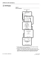
Page 72: ...the current and season miles hours driven in a Pause state 4 Press 4 to enable disable the clearing of the CURRENT TOTALS screen in the Operate mode 5 If GRANULAR or LIQUID is selected from Step 2 above select the material by pressing the corresponding key A divided screen appears showing CURRENT totals top half and SEASON totals bottom half To clear CURRENT totals press C To clear both CURRENT an...

Page 73: ...T C CLR CURRENT PAUSE MILE 0 0 PAUSE HOURS 0 0 SEASON S CLR BOTH PAUSE MILE 0 0 PAUSE HOURS 0 0 ACCUMULATORS SELECT A MENU ITEM 1 LIQUID 1 DISABLED 2 LIQUID 2 DISABLED 3 LIQUID 3 DISABLED 4 LIQUID 4 DISABLED ACCUMULATORS SELECT A MENU ITEM 1 SALT ENABLED 2 SAND DISABLED 3 MIX A DISABLED 4 MIX B DISABLED SAND TOTALS CURRENT C CLR CURRENT TONS AUTO 4 5 MILES AUTO 2 8 HOUR AUTO 3 97 TONS BLAST 4 3 MI...

Page 74: ...MASTER Switch module on off and channel on off with time and date for each event A maximum of the latest 100 events are logged with the oldest events dropping out as new events occur The up down arrow keys scroll the events for viewing and the bottom line of the screen indicates the group of events displaying RATE CHANGE HISTORY Records each occurrence with time and date of target application rate...

Page 75: ...LIQUID 2 APP FROM 7 0 TO 8 0 7 JAN 06 8 23 AM MIX B MIN FROM 200 TO 180 5 JAN 06 2 42 PM SALT MAX FROM 150 TO 120 TRUCK ID TRUCK 15 COUNTY ON OFF HISTORY 24 DEC 98 3 42 PM POWERED ON 26 JAN 06 8 42 AM POWERED ON 27 JAN 06 8 23 AM POWERED ON 31 JAN 06 12 50 PM POWERED ON 1 JAN 06 9 00 AM POWERED ON 4 DEC 98 1 32 PM POWERED ON SYSTEM TOTALS AUTO HOURS 201 42 MILES 8227 9 BLAST HOURS 11 3 MILES 422 5...

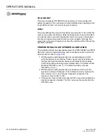
Page 76: ...v B KEYBOARD PROGRAMMING 71 PERFORMING SYSTEM RESPONSE F11 After all configuration constants have been entered for a given vehicle the SYSTEM RESPONSE must be performed in preparation for spreading materials as described in the System Calibration section ...

Page 77: ...OPERATOR S MANUAL Control Point 11001 1489 201702 Rev B 72 KEYBOARD PROGRAMMING ...

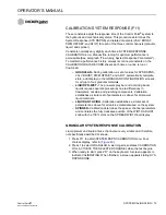
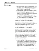
Page 78: ...e results and keyboard enter the constants The SYSTEM RESPONSE CALIBRATION does not require repeating MAINTAINING CALIBRATION ACCURACY The below conditions should be followed to maintain accurate system calibration 1 If a new material is added and the spreader nozzle or flowmeter constant is not accurately known the GRANULAR or LIQUID CALIBRATION routine must be run 2 If wear of the conveyor auger...

Page 79: ...OPERATOR S MANUAL Control Point 11001 1489 201702 Rev B 74 SYSTEM CALIBRATION ...

Page 80: ...ns for all up to four granular materials LIQUID PR WET The pre wet spray bar and anti icing boom liquids require separate procedures due to differences in flowmeters nozzles and plumbing components Calibration establishes a similar set of parameters as above for all pre wet liquid materials LIQUID ANTI ICING Calibration establishes a similar set of parameters as above for all anti ice materials us...

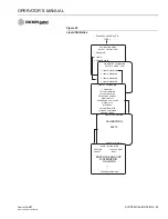
Page 81: ...MENU ITEM 1 GRANULAR 2 LIQUID PRE WET 3 LIQUID ANTI ICING 4 SPINNER SYS RSPNS CALIBRATION GRANULAR WARNING THIS CALIBRATION WILL ACTIVATE THE SELECTED CHANNEL STARTING THIS PROCEDURE WILL CAUSE MATERIAL TO DISPENSE PRESS R TO RUN Press Function Key F11 SYSTEM RESP SYS RSPNS CALIBRATION GRANULAR OPEN FULL PRESS S TO STOP CALIBRATING SYS RSPNS CALIBRATION GRANULAR PRESS C TO CONTINUE SYS RSPNS DONE ...

Page 82: ...c values The following are a few general guidelines Figure 47 Proportional Valve Spinner Calibration Screens SYS RSPNS CONSTANT If the control system responds slowly to changes in speed and is slow to start the SYS RSPNS value should be increased If the system is oscillating around the target APR the SYS RSPNS may be too large and should be decreased Excessive oscillation should be limited to 5 of...

Page 83: ...N This calibration determines appropriate values for PWM OFFSET and PWM SAT when using a proportional valve with no feedback sensor to drive the spinner channel refer to Figure 47 1 With the spinner width adjust knob fully counterclockwise CCW verify the spinner is not rotating These checks must be performed in the Operate mode Rotate the spinner width adjust knob clockwise CW one position and ver...

Page 84: ...eight is adjusted to the proper setting on V Box spreaders If tailgate spreads are in use make sure auger is full Load enough material to provide a uniform flow throughout the calibration procedure 2 Position a suitable container or drop cloth to catch all dispensed material from the conveyor auger The container must be large enough to obtain a good representative sample The larger the sample weig...

Page 85: ...on 0 stop the test and check the application rate sensor CALIBRATION MENU SELECT A MENU ITEM 1 GRANULAR 2 LIQUID 3 SPINNER WIDTH GRANULAR CALIBRATION SELECT A MENU ITEM 1 SALT ENABLED 2 SAND DISABLED 3 MIX A DISABLED 4 MIX B DISABLED SALT CALIBRATION WARNING THIS CALIBRATION WILL ACTIVATE THE SELECTED CHANNEL STARTING THIS PROCEDURE WILL CAUSE MATERIAL TO DISPENSE CATCH MATERIAL IN WEIGHED CONTAIN...

Page 86: ...ich is then keyboard entered on the F3 GRANULAR CONFIGURATION screen Alternatively the GRANULAR CALIBRATION routine can be repeated to correct this type of APR error LIQUID MATERIALS CALIBRATION F6 The LIQUID CALIBRATION determines a flowmeter constant K FACTOR for each liquid material used The K FACTOR represents the number of pulses generated by the flowmeter per gallon of liquid dispensed The N...

Page 87: ...the calibration routine For flowmeter based systems use the liquid channel switch on the Switch Module as necessary to obtain an adequate discharge rate The number displayed indicates the accumulating count from the APR sensor 7 When a sufficient amount of liquid has been dispensed press S to stop For a flowmeter based system a screen appears showing the previous K FACTOR and the sensor counts acc...

Page 88: ... 2 LIQUID DISABLED 3 LIQUID DISABLED 4 LIQUID DISABLED LIQUID 1 CALIBRATION WARNING THIS CALIBRATION WILL ACTIVATE THE SELECTED CHANNEL STARTING THIS PROCEDURE WILL CAUSE MATERIAL TO DISPENSE CATCH MATERIAL IN WEIGHED CONTAINER PRESS R TO RUN LIQUID 1 CALIBRATION CALIBRATING 44910 PRESS S TO STOP LIQUID 1 CALIBRATION K FACTOR 10000 00 P GAL COUNTS 53636 ENTER THE AMOUNT DISPENSED IN GALLONS PRESS ...

Page 89: ...cles vary a multi point calibration is necessary to assure accurate spreading throughout the spinner knob range Also material densities vary requiring separate calibrations 1 Load the vehicle with material 2 Press Function key F6 to access the CALIBRATION MENU Press the 3 key to select SPINNER WIDTH 3 Select a material for calibration Items 1 through 4 The words ENABLED and DISABLED after the sele...

Page 90: ...TEM 1 GRANULAR 2 LIQUID 3 SPINNER WIDTH SPIN WIDTH CALIBRATION SELECT A MENU ITEM 1 SALT ENABLED 2 SAND ENABLED 3 MIX A DISABLED 4 MIX B DISABLED SALT WIDTHS NOT CALIBRATED POSITION 20 0 0 FT POSITION 40 0 0 FT POSITION 60 0 0 FT POSITION 80 0 0 FT POSITION 100 0 0 FT WARNING CALIBRATE STARTS MATERIAL FLOW PRESS R TO RUN Press Function Key F6 CAL ...

Page 91: ...OPERATOR S MANUAL Control Point 11001 1489 201702 Rev B 86 SYSTEM CALIBRATION ...

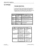
Page 92: ...tors for Servo Conveyor auger and spinner Regulate conveyor auger speed or Proportional Valves hydraulic control valves and spinner speed and liquid flow and Liquid Pump liquid pump rate Harnesses All components Connect all components Table 2 Common Spreader Problems Control System Normal Symptom Probable Cause Corrective Action Conveyor auger does not 1 Hydraulic pump off 1 Engage pump run in eit...

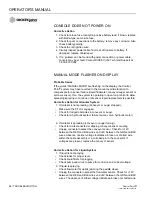
Page 93: ... sensor repair replacement is possible Corrective Action for Granular System 1 If material is not spreading Conveyor or auger stopped Make sure the PTO is engaged Check for lodged obstacles in conveyor or auger Check for a hydraulic system failure pump valve hydraulic motor 2 If material is spreading conveyor or auger turning Check for a disconnected or slipping conveyor sensor coupling Unplug con...

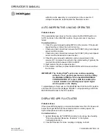
Page 94: ...should be between 35000 to 60000 3 Next replace the ground speed sensor 4 If the failure continues replace the MASTER switch module and then the console IMPORTANT The Control Point system can continue operating without a true ground speed sensor input by setting the MANUAL SPEED to YES in the GROUND SPEED CONFIGURATION F7 screen With this enabled the console simulates an artificial ground speed si...

Page 95: ...em Response SYS RSPNS constant may be too small Refer to Fine tuning System Response Constants section SPINNER ROTATIONAL SPEED INCORRECT Corrective Action 1 Check PWM OFFSET and PWM settings in SPINNER mode F8 for incorrect setting 2 Check for variations in granular material density dropping onto the spinners from the conveyor auger 3 On proportional valves increases in electrical coil resistance...

Page 96: ...s to the valve coil resistance of the coils See manufacturers specifications and verify voltage from control console Corrective Action for Liquid System 1 Check to see if the liquid tanks are low shut off valves are partially closed bypass valves are open too far or an obstruction is in the liquid tank outlet 2 Check filters between the liquid tank and suction side of the liquid pump for blockage ...

Page 97: ...al to the coil the GRY wire is signal ground Voltage reading should be equal to reading in step above If voltages are not present check wiring harnesses for cuts or shorts 3 If voltages are present a hydraulic valve or hydraulic flow problem is indicated 4 If the above checks are normal replace the PWM valve driver If this does not the solve problem replace the console Corrective Action for Granul...

Page 98: ...ld be present Check voltage readings at the pump or solenoid coil on the valve The RED wire supplies the PWM voltage signal to the pump or solenoid coil while the BLK wire is signal ground Voltage reading should be equal to those above 2 If voltages are present but sprayer does not spray the pump solenoid coil hydraulic valve or hydraulic flow may be faulty If voltages are not present check wiring...

Page 99: ... TO UN LO AD MAS TE R 0 0 40 60 80 10 0 BL AS T BRN M Ch 2 w7 P RED 5V w25 L ORG On Off w13 BLK N GND w26 GRN Y Channel 1 w1 X BLU Spinner w21 BRN V Keyboard Data 1 W BLU 5V 4 BLK J Keyboard Clock 5 Z GRN GND 7 S BLK DCD 1 A RED TD 3 B ORG RST 7 C GRN DTR 4 D WHT RD 2 E YEL CTS 8 BRN K GND 5 R BLU DSR 6 VLT T RI 9 F11 F12NumPrt Scl Pau F1 ESC F2 F3 F4 F5 F6 F7 F8 F9 F10 1 2 3 4 5 6 7 8 9 0 Q W E R...

Page 100: ... Sensor 46421 0870S1 GRN C BLK B RED A RED A BLK B LTBLU BK C PUR WHT D Main Harness 46649 0485 46649 0486 Battery Main Power Fuse Flowmeter Application Rate Fq Sensor 46436 017xS1 e 37 WHT Flowmeter Liquid Fq Freq Signal g 24 ORG BK Spinner Fq Freq Signal E 32 LTGRN Spinner open p 26 LTBLU Granular open n 20 ORG 12V Switched Output r 35 PUR WHT Air Temp Ang Signal z 28 GRY Tank Level Analog Signa...

Page 101: ... 38 RED WHT BRN WH RED GRY 9 21 12 6 39 BLK PNK WHT BLK 47 32 33 26 TAN VIL A C B E D F PLUG AUX WHT BLU GRN BLK RED BRN GRN BLK RED GRN RED BLK BLK GRN RED POWER 1 3 2 4 9 8 B A C GATE HEIGHT FLOW METER SPINNER SENSOR A C B B C A WHT RED GRY PLUG WHT RED BLK BRN GN BLK GN BLK RED BLK BLK LIQUID VALVE F E B A C D VALVE 2 1 3 16 14 15 VLT 8 PNK 6 TAN 5 WHT BLK 4 RED A BLK B 28 GRY Tank Level GRN C ...

Page 102: ... 300 LBS MILE but Actual APR is known to be 315 LBS MILE adjust SPR CON using the above formula NOTE Keyboard enter the new SPR CON on the appropriate Granular configuration screen Adjusting Liquid Constants In a manner similar to that for granular shown above liquid APR errors can be corrected by fine tuning the flowmeter constant K FACTOR as follows EXAMPLE If K FACTOR is 1 000 and Target APR is...

Page 103: ... per revolution of the final shaft EXAMPLE A 360 pulses per revolution for Dj sensor p n 46436 017X B 25 turns of the sensor shaft for each turn of the final shaft C 50 pounds of material discharged per revolution of final shaft NOTES 1 V Box spreaders have a different SPR CON for each gate setting 2 The number of pulses per revolution for several Dj shaft sensors are 360 for p n 46436 017X standa...

Page 104: ...__________ RATE 5 __________ __________ __________ __________ RATE 6 __________ __________ __________ __________ RATE 7 __________ __________ __________ __________ RATE 8 __________ __________ __________ __________ RATE 9 __________ __________ __________ __________ RATE 10 __________ __________ __________ __________ BLST RATE __________ __________ __________ __________ CHN LBL __________ _________...

Page 105: ..._______ __________ DRV FREQ __________ __________ __________ __________ PWM OFFSET __________ __________ __________ __________ PWM SAT __________ __________ __________ __________ SYS RSPNS __________ __________ __________ __________ VALV BOOST __________ __________ __________ __________ AFILT __________ __________ __________ __________ TANK LEVEL __________ __________ __________ __________ VALVE L...

Page 106: ...__________ __________ RATE 5 __________ __________ __________ __________ RATE 6 __________ __________ __________ __________ RATE 7 __________ __________ __________ __________ RATE 8 __________ __________ __________ __________ RATE 9 __________ __________ __________ __________ RATE 10 __________ __________ __________ __________ BLST RATE __________ __________ __________ __________ CHN LBL _________...

Page 107: ...__ __________ DRV FREQ __________ __________ __________ __________ PWM OFFSET __________ __________ __________ __________ PWM SAT __________ __________ __________ __________ SYS RSPNS __________ __________ __________ __________ VALV BOOST __________ __________ __________ __________ AFILT __________ __________ __________ __________ TANK LEVEL __________ __________ __________ __________ VALVE LOCK _...

Page 108: ...r special damages Said part will not be considered defective if it substantially fulfills the performance expectations THE FOREGOING WARRANTY IS EXCLUSIVE AND IN LIEU OF ALL OTHER WARRANTIES OF MERCHANTABILITY FITNESS FOR PURPOSE AND OF ANY OTHER TYPE WHETHER EXPRESS OR IMPLIED DICKEY john neither assumes nor authorizes anyone to assume for it any other obligation or liability in connection with s...

Page 109: ...2 Rev B Operator s Manual 5200 Dickey john Road Auburn IL 62615 www dickey john com 217 438 3371 217 438 6012 fax 2017 DICKEY john DICKEY john Sales 800 637 2952 agsales dickey john com DICKEY john Technical Support 800 637 3302 service dickey john com Europe Sales and Technical Support 33 1 41 19 21 80 europe dickey john com SINCE 1966 ...

Reviews: