Notes, Cautions, and Warnings
NOTE:
A NOTE indicates important information that helps you make better
use of your product.
CAUTION:
A CAUTION indicates either potential damage to hardware or
loss of data, and tells you how to avoid the problem.
WARNING:
A WARNING indicates a potential for property damage,
personal injury, or death.
____________________
Information in this document is subject to change without notice.
© 2011 Dell Inc. All rights reserved.
Reproduction of these materials in any manner whatsoever without the written permission of Dell Inc.
is strictly forbidden.
Trademarks used in this text: Dell™ and the DELL logo are trademarks of Dell Inc. Alienware
®
is a
registered trademark of Alienware Corporation. Microsoft
®
, Windows
®
, and the Windows start button
logo are either trademarks or registered trademarks of Microsoft Corporation in the United States and/
or other countries.
Other trademarks and trade names may be used in this document to refer to either the entities claiming
the marks and names or their products. Dell Inc. disclaims any proprietary interest in trademarks and
trade names other than its own.
2011 - 12
Rev. A00
book.book Page 2 Wednesday, May 16, 2012 2:37 PM
Summary of Contents for Alienware Aurora R4
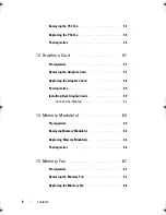
Page 16: ...16 Before you Begin ...
Page 24: ...24 Technical Overview ...
Page 28: ...28 Left Side Panel ...
Page 31: ...Hard Drive s 31 2 Follow the steps in After Working Inside Your Computer on page 15 ...
Page 32: ...32 Hard Drive s ...
Page 36: ...36 Hard Drive Fan Assembly ...
Page 39: ...Optical Drive s 39 2 Follow the steps in After Working Inside Your Computer on page 15 ...
Page 40: ...40 Optical Drive s ...
Page 56: ...56 PCI Fan Assembly ...
Page 62: ...62 Graphics Card ...
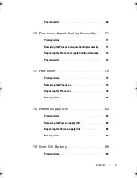
Page 69: ...Memory Fan 69 2 Follow the steps in After Working Inside Your Computer on page 15 ...
Page 70: ...70 Memory Fan ...
Page 74: ...74 Processor Liquid Cooling Assembly ...
Page 81: ...Processor 81 ...
Page 82: ...82 Processor ...
Page 88: ...88 Power Supply ...
Page 92: ...92 Coin Cell Battery ...
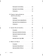
Page 98: ...98 System Board Assembly ...
Page 102: ...102 Master I O Board ...
Page 106: ...106 Top Lighting Board ...
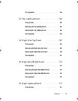
Page 108: ...108 Right Side Top Panel 2 Remove the screw that secures the right side top panel ...
Page 112: ...112 Right Side Top Panel ...
Page 116: ...116 Right Side Middle Panel ...
Page 120: ...120 Right Lighting Board ...
Page 135: ...Back Bezel 135 1 screws 2 2 back bezel 3 tabs 1 2 3 ...
Page 140: ...140 WiFi Bluetooth Assembly ...
Page 144: ...144 Top I O Panel ...
Page 158: ...158 System Setup Utility ...
Page 162: ...162 Specifications ...


