150
System Setup Utility
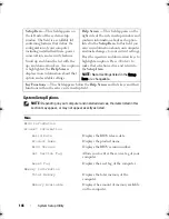
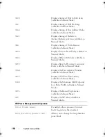
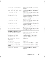
tRCD
Displays timing of RAS to CAS delay
(editable in Manual Mode).
tRP
Displays timing of RAS Precharge
(editable in Manual Mode).
tRAS
Displays timing of Row Address Strobe
(editable in Manual Mode).
tRFC
Displays timing of Refresh to
Archive/Refresh cycle time (editable in
Manual Mode).
tWR
Displays timing of Write Recover
(editable in Manual Mode).
tWTR
Displays Write to Read Delay (editable in
Manual Mode).
tRRD
Displays RAS to RAS delay (editable in
Manual Mode).
tRTP
Displays Read to Precharge Command
Delay (editable in Manual Mode).
tFAW
Displays the Four Activate Window
(editable in Manual Mode).
tWCL
Displays the Write CAS Latency
(editable in Manual Mode).
tCKE
Displays the Minimum CKE High and
Low Pulse Width (editable in Manual
Mode).
tRTL
Displays the Round Trip Latency
(editable in Manual Mode).
tXP
Displays the XP value (editable in
Manual Mode).
CPU Power Management Configuration
Intel Turbo Boost
If enabled, allows processor to run at
faster frequencies than marked.
Long duration power limit
Allows you to change the long duration
power limit.
book.book Page 150 Wednesday, May 16, 2012 2:37 PM
Summary of Contents for Alienware Aurora R4
Page 16: ...16 Before you Begin ...
Page 24: ...24 Technical Overview ...
Page 28: ...28 Left Side Panel ...
Page 31: ...Hard Drive s 31 2 Follow the steps in After Working Inside Your Computer on page 15 ...
Page 32: ...32 Hard Drive s ...
Page 36: ...36 Hard Drive Fan Assembly ...
Page 39: ...Optical Drive s 39 2 Follow the steps in After Working Inside Your Computer on page 15 ...
Page 40: ...40 Optical Drive s ...
Page 56: ...56 PCI Fan Assembly ...
Page 62: ...62 Graphics Card ...
Page 69: ...Memory Fan 69 2 Follow the steps in After Working Inside Your Computer on page 15 ...
Page 70: ...70 Memory Fan ...
Page 74: ...74 Processor Liquid Cooling Assembly ...
Page 81: ...Processor 81 ...
Page 82: ...82 Processor ...
Page 88: ...88 Power Supply ...
Page 92: ...92 Coin Cell Battery ...
Page 98: ...98 System Board Assembly ...
Page 102: ...102 Master I O Board ...
Page 106: ...106 Top Lighting Board ...
Page 108: ...108 Right Side Top Panel 2 Remove the screw that secures the right side top panel ...
Page 112: ...112 Right Side Top Panel ...
Page 116: ...116 Right Side Middle Panel ...
Page 120: ...120 Right Lighting Board ...
Page 135: ...Back Bezel 135 1 screws 2 2 back bezel 3 tabs 1 2 3 ...
Page 140: ...140 WiFi Bluetooth Assembly ...
Page 144: ...144 Top I O Panel ...
Page 158: ...158 System Setup Utility ...
Page 162: ...162 Specifications ...

