
Top I/O Panel
141
30
Top I/O Panel
WARNING:
Before working inside your computer, read the safety information
that shipped with your computer and follow the steps in "Before You Begin" on
page 13. For additional safety best practices information, see the Regulatory
Compliance Homepage at dell.com/regulatory_compliance.
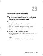
Prerequisites
1
Remove the left side-panel. See "Removing the Left Side-Panel" on
page 25.
2
Open the PCI shroud. See "Opening the PCI Shroud" on page 45.
3
Remove the drive-bay shroud. See "Removing the Drive-Bay Shroud" on
page 47.
4
Remove the PCI-Express x1 card. See "Removing the PCI-Express x1
Card" on page 49.
5
Remove the graphics card. See "Removing the Graphics Card" on page 57.
6
Remove the PCI-fan. See "Removing the PCI-Fan" on page 53.
7
Remove the right-side top panel. See "Removing the Right-Side Top
Panel" on page 107.
8
Remove the right lighting-board. See "Removing the Right Lighting-
Board" on page 117.
9
Remove the right-side middle panel. See "Removing the Right-Side
Middle Panel" on page 113.
10
Remove the right-side bottom panel. See "Removing the Right-Side
Bottom Panel" on page 121.
11
Remove the front bezel. See "Removing the Front Bezel" on page 129.
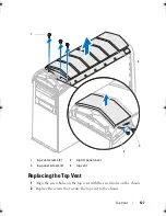
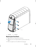
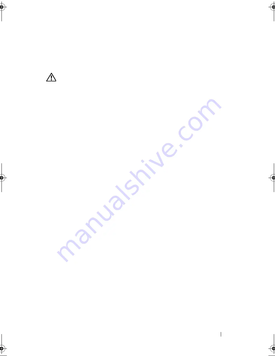
Removing the Top I/O Panel
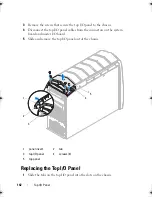
1
Push the tab on the panel insert to release the panel insert from the slot on
the chassis.
2
Pull the panel insert away from the chassis.
book.book Page 141 Wednesday, May 16, 2012 2:37 PM
Summary of Contents for Alienware Aurora R4
Page 16: ...16 Before you Begin ...
Page 24: ...24 Technical Overview ...
Page 28: ...28 Left Side Panel ...
Page 31: ...Hard Drive s 31 2 Follow the steps in After Working Inside Your Computer on page 15 ...
Page 32: ...32 Hard Drive s ...
Page 36: ...36 Hard Drive Fan Assembly ...
Page 39: ...Optical Drive s 39 2 Follow the steps in After Working Inside Your Computer on page 15 ...
Page 40: ...40 Optical Drive s ...
Page 56: ...56 PCI Fan Assembly ...
Page 62: ...62 Graphics Card ...
Page 69: ...Memory Fan 69 2 Follow the steps in After Working Inside Your Computer on page 15 ...
Page 70: ...70 Memory Fan ...
Page 74: ...74 Processor Liquid Cooling Assembly ...
Page 81: ...Processor 81 ...
Page 82: ...82 Processor ...
Page 88: ...88 Power Supply ...
Page 92: ...92 Coin Cell Battery ...
Page 98: ...98 System Board Assembly ...
Page 102: ...102 Master I O Board ...
Page 106: ...106 Top Lighting Board ...
Page 108: ...108 Right Side Top Panel 2 Remove the screw that secures the right side top panel ...
Page 112: ...112 Right Side Top Panel ...
Page 116: ...116 Right Side Middle Panel ...
Page 120: ...120 Right Lighting Board ...
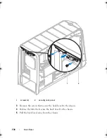
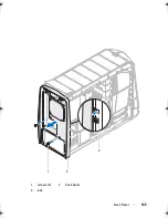
Page 135: ...Back Bezel 135 1 screws 2 2 back bezel 3 tabs 1 2 3 ...
Page 140: ...140 WiFi Bluetooth Assembly ...
Page 144: ...144 Top I O Panel ...
Page 158: ...158 System Setup Utility ...
Page 162: ...162 Specifications ...