


SiENBE18-621
iv
Index
N
N .............................................................................24
N1 ...........................................................................29
N2 ...........................................................................29
NA ..........................................................................27
names of parts .....................................................155
NB ..........................................................................27
NC ..........................................................................24
night set mode ........................................................90
noise filter PCB (A3P) ............................................27
normal operation ....................................................61
O
oil return operation .................................................68
ON/OFF button on indoor unit ................................96
operation lamp .....................................................251
operation mode ......................................................60
outdoor unit identification function ........................101
outdoor unit PCB layout .......................................117
OUTDOOR UNIT SILENT operation ....................189
outdoor unit thermistors for discharge pipe ..........356
P
P .............................................................................24
P1 .........................................................................332
P4 .........................................................................333
photocatalytic deodorizing filter ..............................96
piping diagrams ....................................................362
PJ .........................................................................334
power failure recovery
function .............................30, 33, 35, 37, 39, 42
power supply insufficient or
instantaneous failure .....................................337
power supply PCB ............................................40, 43
power supply waveforms check ...........................306
power-airflow dual flaps .........................................85
POWERFUL operation .........................................188
preparation before operation ................................173
pressure sensor ...................................................357
printed circuit board (PCB)
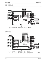
BP unit PCB .....................................................29
buzzer PCB .....................................................36
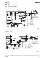
control PCB (indoor unit)
................................31, 34, 36, 37, 40, 44, 46, 48
cool/heat selector PCB (A4P) ..........................28
display PCB .............................32, 36, 38, 41, 44
INTELLIGENT EYE sensor PCB .........32, 34, 36
main PCB (A1P) ..............................................25
noise filter PCB (A3P) ......................................27
power supply PCB .....................................40, 43
service PCB (A2P) ...........................................26
signal receiver PCB .................32, 34, 36, 41, 44
printed circuit board connector wiring diagram ......24
program dry operation function ............................106
programme dry function .........................................87
protection control ....................................................73
pump-down residual operation ...............................71
R
refrigerant circuit ....................................................50
refrigerant flow for each operation mode ...............54
refrigerant overcharged ....................................... 317
refrigerant recovery mode ................................... 134
remote control ..................................................... 255
remote control thermistor .................................... 294
remote control thermostat ................................... 105
restart standby ...................................................... 71
RTH1 ................................................... 30, 33, 35, 37
S
S1 ........................................................ 30, 33, 35, 37
S201 ...................................................................... 42
S202 ...................................................................... 42
S203 ...................................................................... 42
S204 ...................................................................... 42
S21 .......................................... 30, 33, 35, 37, 39, 42
S23 ........................................................................ 42
S24 .................................................................. 39, 42
S25 .................................................................. 39, 42
S26 .......................................... 30, 33, 35, 37, 39, 42
S27 ...................................................... 30, 33, 35, 39
S28 .................................................................. 30, 35
S29 .................................................................. 30, 35
S301 ...................................................................... 42
S302 ...................................................................... 42
S31 .................................................................. 39, 42
S32 .......................................... 30, 33, 35, 37, 39, 42
S35 ............................................................ 30, 33, 35
S36 ...................................................... 30, 33, 35, 39
S37 .................................................................. 35, 39
S38 ........................................................................ 35
S6 .................................................. 30, 33, 35, 39, 42
S7 ........................................................ 33, 37, 39, 42
S8 .................................................................... 35, 42
safety precautions ............................................... 153
SC control in heating operation ............................. 84
self-diagnosis by wired remote control ................ 260
self-diagnosis by infrared remote control ............ 261
self-diagnosis digital display .................................. 97
sensor data display ............................................. 145
service check function ......................................... 255
service PCB (A2P) ................................................ 26
setting by dip switches ........................................ 118
setting by pushbutton switches ........................... 120
setting of low noise operation and
demand operation ........................................ 129
setting of refrigerant additional charging
operation ...................................................... 133
SH control in cooling operation ............................. 83
shutter drive motor /
shutter limit switch abnormality .................... 277
signal receiver PCB ....................... 32, 34, 36, 41, 44
signal receiving sign .............................................. 96
special control ....................................................... 67
specifications ......................................................... 10
startup control ....................................................... 67
stopping operation ................................................. 72
suction air thermistor ........................................... 293
SW1 .............................................. 30, 35, 37, 39, 42
SW2 ................................................................ 39, 42
SW4 ...................................................................... 42
SW7 ...................................................................... 33
Summary of Contents for BPMKS967B2B
Page 1: ...SiENBE18 621 E Series Service Manual Applied Models Super Multi Plus Heat Pump...
Page 12: ...SiENBE18 621 List of Functions 1 Part 1 List of Functions 1 List of Functions 2...
Page 19: ...List of Functions SiENBE18 621 8 List of Functions...
Page 33: ...Specifications SiENBE18 621 22 Specifications...
Page 69: ...Refrigerant Flow for Each Operation Mode SiENBE18 621 58 Refrigerant Circuit...
Page 121: ...Indoor Unit SkyAir Models SiENBE18 621 110 Function...
Page 169: ...Instruction SiENBE18 621 158 System Configuration FTXS 20 25 35C Indoor Unit...
Page 371: ...Method of Replacing The Inverter s Power Transistors Modules SiENBE18 621 360 Troubleshooting...
Page 393: ...SiENBE18 621 vi Index...


