


Instruction
SiEN18-621
228
System Configuration
This operation manual is for the following systems with
standard control. Before initiating operation, contact your
Daikin dealer for the operation that corresponds to your
system.
•
Pair system
•
Multi system
NOTE
•
If the unit you purchased is controlled by a infrared
remote control, also refer to the infrared remote
control’s operation manual.
If your installation has a customized control system, ask your
Daikin dealer for operation that corresponds to your system.
•
Heat pump type
This system provides cooling, heating, automatic, program
dry, and fan operation modes.
•
Cooling only type
This system provides cooling, program dry, and fan
operation modes.
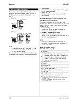
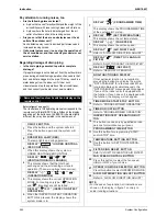
Precautions for group control system or two
remote control control system
This system provides two other control systems beside
individual control (one remote control controls one indoor unit)
system. Confirm the following if your unit is of the following
control sytem type.
•
Group control system
One remote control controls up to 16 indoor units.
All indoor units are equally set.
•
Two remote controls control system
Two remote controls control one indoor unit
(In case of group control sytem, one group of indoor units)
The unit is individually operated.
NOTE
•
Contact your Daikin dealer in case of changing the
combination or setting of group control and two remote
controls control sytem.
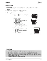
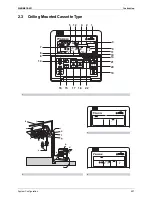
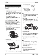
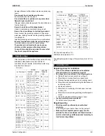
Names and functions of parts
Refer to figure 2 on page [1]
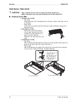
1. What to do before operation
Indoor
u
nit
O
u
tdoor
u
nit
Unit with
remote
control
Indoor
u
nit
O
u
tdoor
u
nit
Unit with
remote
control
Unit with
remote
control
Indoor
u
nit
a
Indoor unit
b
Outdoor unit
•
The external appearance of the outdoor unit varies
depending on its capacity class. The outdoor unit
shown in the figure is for reference to indicate
features. Contact your Daikin Dealer and verify
which outdoor unit you have.
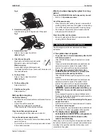
c
Remote control
d
Inlet air
e
Discharged air
f
Air outlet
g
Air flow flap (at air outlet)
h
Refrigerant piping, connection electric wire
i
Drain pipe
j
Air inlet
The built-in air filter removes dust and dirt.
k
Drain pumping out device (built-in)
Drains water removed from the room during cooling.
l
Ground wire
Wire to ground from the outdoor unit to prevent
electrical shocks.
Summary of Contents for BPMKS967B2B
Page 1: ...SiENBE18 621 E Series Service Manual Applied Models Super Multi Plus Heat Pump...
Page 12: ...SiENBE18 621 List of Functions 1 Part 1 List of Functions 1 List of Functions 2...
Page 19: ...List of Functions SiENBE18 621 8 List of Functions...
Page 33: ...Specifications SiENBE18 621 22 Specifications...
Page 69: ...Refrigerant Flow for Each Operation Mode SiENBE18 621 58 Refrigerant Circuit...
Page 121: ...Indoor Unit SkyAir Models SiENBE18 621 110 Function...
Page 169: ...Instruction SiENBE18 621 158 System Configuration FTXS 20 25 35C Indoor Unit...
Page 371: ...Method of Replacing The Inverter s Power Transistors Modules SiENBE18 621 360 Troubleshooting...
Page 393: ...SiENBE18 621 vi Index...


