


SiENBE18-621
Index
i
Index
A
A1 .................................................................270, 281
A1P ........................................................................25
A2P ........................................................................26
A3 .........................................................................282
A3P ........................................................................27
A4P ........................................................................28
A5 .........................................................................271
A6 .................................................273, 274, 285, 286
A7 .........................................................................288
A9 .........................................................................300
abnormal discharge pipe temperature .................316
actuation of high pressure switch .........................308
actuation of low pressure switch ..........................310
address duplication of central
remote control ...............................................347
address setting jumper .............30, 33, 35, 37, 39, 42
adjusting the air flow direction ..............................178
AF .........................................................................284
air purifying filter .....................................................96
air purifying filter with photocatalytic deodorizing
function ...........................................................97
AJ .........................................................................290
ARC433A .............................................................255
AUTO · DRY · COOL · HEAT · FAN operation .....176
automatic air flow control .......................................86
automatic operation ................................................88
auto-restart .............................................................30
auto-restart function .......................................97, 106
auto-swing ..............................................................85
B
BP unit command conversion ................................80
BP unit control ........................................................80
BP unit electronic expansion valve control .............81
BP unit PCB ...........................................................29
BS1 ........................................................................26
BS2 ........................................................................26
BS3 ........................................................................26
BS4 ........................................................................26
BS5 ........................................................................26
buzzer PCB ............................................................36
C
C4 .................................................................276, 291
C5 .........................................................................292
C7 .........................................................................277
C9 .................................................................276, 293
care and cleaning .................................................203
centralized control ..........................30, 33, 35, 37, 39
centralized group No. setting ...............................144
check
check for causes of drop in low pressure ......353
check for causes of rise in high pressure ......352
check for fan motor connector .......................354
fan motor connector output check ........ 278, 298
Hall IC check ................................................. 280
limit switch continuity check .......................... 278
power supply waveforms check .................... 306
thermistor resistance check .................. 279, 299
check for causes of drop in low pressure ............ 353
check for causes of rise in high pressure ............ 352
check for fan motor connector ............................. 354
check operation ........................................... 115, 135
check operation not executed ............................. 339
CJ ........................................................................ 294
compressor motor lock ........................................ 312
compressor PI control ........................................... 62
condensation avoidance control (FHQ only) ....... 101
connectors ............................................................. 24
control PCB
(indoor unit) .......... 31, 34, 36, 37, 40, 44, 46, 48
cool/heat mode switching .................................... 127
cool/heat selector PCB (A4P) ............................... 28
cooling operation fan control ................................. 66
D
defrosting operation .............................................. 70
demand operation ................................................. 79
dew condensation prevention control .................... 78
dew prevention fan control .................................. 109
diagnosis mode ................................................... 256
discharge pipe protection control .......................... 75
display PCB ................................... 32, 36, 38, 41, 44
drain pump control .............................................. 101
DS1 ....................................................................... 26
E
E ............................................................................ 27
E1 ........................................................................ 307
E2 ........................................................................ 301
E3 ........................................................................ 308
E4 ........................................................................ 310
E5 ........................................................................ 312
E7 ........................................................................ 313
E9 ........................................................................ 314
econo mode .......................................................... 91
econo operation .................................................. 190
electric function parts ............................................ 99
electronic expansion valve PI control .................... 65
error codes
A1 ......................................................... 270, 281
A3 ................................................................. 282
A5 ................................................................. 271
A6 ......................................... 273, 274, 285, 286
A7 ................................................................. 288
A9 ................................................................. 300
AF ................................................................. 284
AJ .................................................................. 290
C4 ......................................................... 276, 291
Summary of Contents for BPMKS967B2B
Page 1: ...SiENBE18 621 E Series Service Manual Applied Models Super Multi Plus Heat Pump...
Page 12: ...SiENBE18 621 List of Functions 1 Part 1 List of Functions 1 List of Functions 2...
Page 19: ...List of Functions SiENBE18 621 8 List of Functions...
Page 33: ...Specifications SiENBE18 621 22 Specifications...
Page 69: ...Refrigerant Flow for Each Operation Mode SiENBE18 621 58 Refrigerant Circuit...
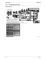
Page 121: ...Indoor Unit SkyAir Models SiENBE18 621 110 Function...
Page 169: ...Instruction SiENBE18 621 158 System Configuration FTXS 20 25 35C Indoor Unit...
Page 371: ...Method of Replacing The Inverter s Power Transistors Modules SiENBE18 621 360 Troubleshooting...
Page 393: ...SiENBE18 621 vi Index...


