


SiENBE18-621
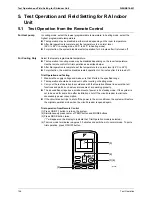
Field Setting for SkyAir Indoor Unit
Test Operation
145
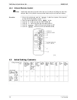
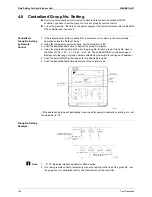
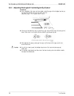
4.7
Maintenance Mode Setting
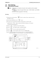
Procedure
1. Enter the field set mode.
Continue to push the inspection / test operation button for a minimum of 4 seconds.
2. Enter the maintenance mode.
After having entered the field set mode, continue to push the inspection / test operation
button for a minimum of 4 seconds.
3. Select the mode No.
Set the desired mode No. with the up/down temperature setting button.
4. Select the unit No.
Select the indoor unit No. set with the time mode START/STOP button.
5. Carry out the necessary settings for each mode. (Modes 41, 44 and 45)
See the table below for details.
6. Enter the setting contents. (Modes 44 and 45)
Enter by pushing the timer ON/OFF button.
7. Return to the normal operation mode.
Tap the inspection / test operation button one time.
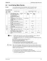
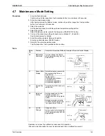
Table
Operation is not reset by malfunction code reset for inspection.
(Cannot be reset because the count is updated each time a malfunction occurs.)
Mode
No.
Function
Content and Operation Method Example of Remote Control Display
40
Malfunction
Hysteresis
You can change the history
with the programming time up-
down button.
41
Sensor Data
Display
Select the display sensor with
the programming time up-
down button
Display sensor
00
Remote control sensor
01
Suction (R1T)
02
Heat exchange(R2T)
03
Heat exchange(R3T)
43
Forced Fan
ON
Turns the fan ON for each unit
individually.
44
Individual
Setting
Sets fan speed and air flow
direction for each unit
individually when using group
control.
Settings are made using the
“air flow direction adjust” and
“fan speed adjust” buttons.
45
Unit No.
Change
Changes unit No.
Set the unit No. after changing
with the programming time up-
down button.
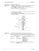
P
as
t m
a
lf
u
nction
code
M
a
lf
u
nction
hy
s
tere
s
i
s
1: Newe
s
t
3
: Olde
s
t
“
00
”
di
s
pl
a
yed for 4
a
nd
subs
e
qu
ent
UNIT No.
CODE
S
ETTING
UNIT No.
S
ETTING
S
en
s
or type
Temper
a
t
u
re
S
ETTING
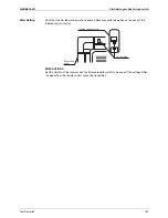
UNIT No.
Air flow direction
1 : Low
0: Upper
4: Lowe
s
t
UNIT No.
CODE
S
ETTING
3
: High
F
a
n
s
peed
Field
s
et No.
UNIT No.
CODE
S
ETTING
No.
a
fter ch
a
nge
Summary of Contents for BPMKS967B2B
Page 1: ...SiENBE18 621 E Series Service Manual Applied Models Super Multi Plus Heat Pump...
Page 12: ...SiENBE18 621 List of Functions 1 Part 1 List of Functions 1 List of Functions 2...
Page 19: ...List of Functions SiENBE18 621 8 List of Functions...
Page 33: ...Specifications SiENBE18 621 22 Specifications...
Page 69: ...Refrigerant Flow for Each Operation Mode SiENBE18 621 58 Refrigerant Circuit...
Page 121: ...Indoor Unit SkyAir Models SiENBE18 621 110 Function...
Page 169: ...Instruction SiENBE18 621 158 System Configuration FTXS 20 25 35C Indoor Unit...
Page 371: ...Method of Replacing The Inverter s Power Transistors Modules SiENBE18 621 360 Troubleshooting...
Page 393: ...SiENBE18 621 vi Index...


