


SiENBE18-621
250
Troubleshooting
7. Troubleshooting for Outdoor Unit........................................................307
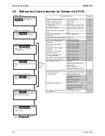
7.1
Faulty Outdoor Unit PCB......................................................................307
7.2
Actuation of High Pressure Switch .......................................................308
7.3
Actuation of Low Pressure Sensor .......................................................310
7.4
Compressor Motor Lock .......................................................................312
7.5
Malfunction of Outdoor Unit Fan Motor ................................................313
7.6
Malfunction of Moving Part of Electronic Expansion Valve
(Y1E, Y3E) ...........................................................................................314
7.7
Abnormal Discharge Pipe Temperature ...............................................316
7.8
Refrigerant Overcharged......................................................................317
7.9
Malfunction of Thermistor for Outdoor Air (R1T) ..................................318
7.10 Malfunction of Discharge Pipe Thermistor (R2T) .................................319
7.11 Malfunction of Thermistor (R3T, R5T) for Suction Pipe1, 2 .................320
7.12 Malfunction of Thermistor (R4T) for Outdoor Unit Heat Exchanger .....321
7.13 Malfunction of Thermistor (R7T) for Outdoor Unit Liquid Pipe .............322
7.14 Malfunction of Subcooling Heat Exchanger Thermistor (R6T) .............323
7.15 Malfunction of High Pressure Sensor...................................................324
7.16 Malfunction of Low Pressure Sensor....................................................325
7.17 Malfunction of PCB...............................................................................326
7.18 Malfunction of Inverter Radiating Fin Temperature Rise......................327
7.19 Inverter Compressor Abnormal ............................................................328
7.20 Inverter Current Abnormal....................................................................329
7.21 Inverter Start up Error...........................................................................330
7.22 Malfunction of Transmission between Inverter and Control PCB .........331
7.23 High Voltage of Capacitor in Main Inverter Circuit ...............................332
7.24 Malfunction of Inverter Radiating Fin Temperature Rise Sensor .........333
7.25 Faulty Combination of Inverter and Fan Driver ....................................334
7.26 Low Pressure Drop Due to Refrigerant Shortage or
Electronic Expansion Valve Failure......................................................335
7.27 Power Supply Insufficient or Instantaneous Failure .............................337
7.28 Check Operation not Executed ............................................................339
7.29 Malfunction of Transmission between Indoor Units and
Outdoor Units .......................................................................................340
7.30 Malfunction of Transmission between Remote Control and
Indoor Unit............................................................................................342
7.31 Malfunction of Transmission between Main and Sub
Remote Controls ..................................................................................343
7.32 Malfunction of Transmission between Indoor and Outdoor Units
in the Same System .............................................................................344
7.33 Excessive Number of Indoor Units .......................................................346
7.34 Address Duplication of Central Remote Control...................................347
7.35 Malfunction of Transmission between Central Remote
Controller and Indoor Unit ....................................................................348
7.36 System is not Set yet............................................................................350
7.37 Malfunction of System, Refrigerant System Address Undefined..........351
8. Check ..................................................................................................352
9. Thermistor Resistance / Temperature Characteristics ........................355
10.Pressure Sensor .................................................................................357
11.Method of Replacing The Inverter’s Power Transistors Modules........358
Summary of Contents for BPMKS967B2B
Page 1: ...SiENBE18 621 E Series Service Manual Applied Models Super Multi Plus Heat Pump...
Page 12: ...SiENBE18 621 List of Functions 1 Part 1 List of Functions 1 List of Functions 2...
Page 19: ...List of Functions SiENBE18 621 8 List of Functions...
Page 33: ...Specifications SiENBE18 621 22 Specifications...
Page 69: ...Refrigerant Flow for Each Operation Mode SiENBE18 621 58 Refrigerant Circuit...
Page 121: ...Indoor Unit SkyAir Models SiENBE18 621 110 Function...
Page 169: ...Instruction SiENBE18 621 158 System Configuration FTXS 20 25 35C Indoor Unit...
Page 371: ...Method of Replacing The Inverter s Power Transistors Modules SiENBE18 621 360 Troubleshooting...
Page 393: ...SiENBE18 621 vi Index...


