


SiENBE18-621
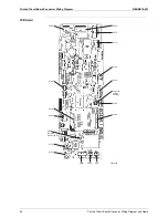
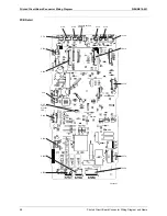
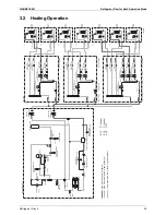
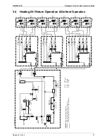
Printed Circuit Board Connector Wiring Diagram
Printed Circuit Board Connector Wiring Diagram and Name
45
1.9
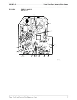
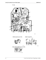
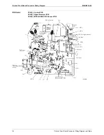
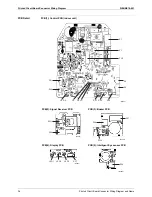
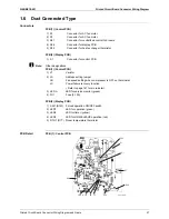
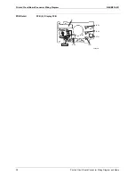
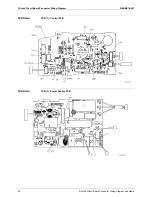
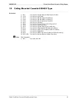
Ceiling Mounted Cassette 600×600 Type
Connectors
1) X5A
Connector for Terminal Strip (for Wired Remote Control)
2) X15A
Connector for Float Switch
3) X17A
Connector for Heat Exchanger Thermistor (2)
4) X18A
Connector for Heat Exchanger Thermistor (1)
5) X19A
Connector for Room Temperature Thermistor
6) X20A
Connector for Fan Motor
7) X24A
Connector for Infrared Remote Control Receiver Unit
8) X25A
Connector for Drain Pump Motor
9) X27A
Connector for Terminal Strip (for Inter Unit Wiring)
10) X33A
Connector for Wring Adapter PCB (Optional Accessory)
11) X35A
Connector for Group Control Adapter (Optional Accessory)
12) X36A
Connector for Swing Motor
13) X40A
Connector for ON/OFF Input from Outside (for Optional Accessory)
14) X60A, X61A
Connector for Interface Adapter (Optional Accessory)
Note:
Other Designation
1) HAP
Service Monitor LED
Summary of Contents for BPMKS967B2B
Page 1: ...SiENBE18 621 E Series Service Manual Applied Models Super Multi Plus Heat Pump...
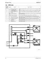
Page 12: ...SiENBE18 621 List of Functions 1 Part 1 List of Functions 1 List of Functions 2...
Page 19: ...List of Functions SiENBE18 621 8 List of Functions...
Page 33: ...Specifications SiENBE18 621 22 Specifications...
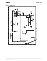
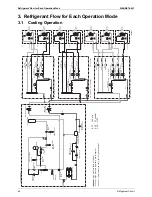
Page 69: ...Refrigerant Flow for Each Operation Mode SiENBE18 621 58 Refrigerant Circuit...
Page 121: ...Indoor Unit SkyAir Models SiENBE18 621 110 Function...
Page 169: ...Instruction SiENBE18 621 158 System Configuration FTXS 20 25 35C Indoor Unit...
Page 371: ...Method of Replacing The Inverter s Power Transistors Modules SiENBE18 621 360 Troubleshooting...
Page 393: ...SiENBE18 621 vi Index...


