ENGLISH
42
In specific calibration conditions, after a power failure the converter may start automatically.
Do not operate the appliance when exposed to direct sunlight.
This appliance may not be used as an “EMERGENCY STOP mechanism” (see EN 60204, 9.2.5.4).
1.3
APPLICATIONS
The ACTIVE DRIVER is supplied already set up for installation in the following models:
−
ACTIVE DRIVER M/T: powered with a single-phase line, controls electric pumps with a 230V
standard three-phase asynchronous motor.
−
ACTIVE DRIVER T/T: powered with a three-phase line, controls electric pumps with a 400V
standard three-phase asynchronous motor.
1.4
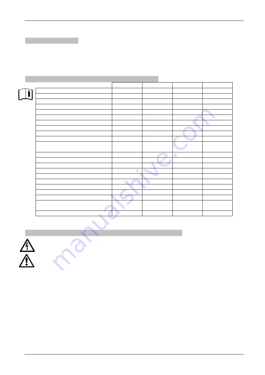
TECHNICAL DATA AND LIMITATIONS OF USE
A.D. M/T 1.0
A.D. M/T 2.2
A.D. T/T 3.0
A.D T/T 5.5
Max. phase current of the motor:
4.7 A
10.5 A
7.5 A
13.3 A
Line voltage (+10% - 20%):
1 x 230 V
1 x 230 V
3 x 400 V
3 x 400 V
Line frequency:
50-60 Hz
50-60 Hz
50-60 Hz
50-60 Hz
Electric pump voltage:
3 x 230 V
3 x 230 V
3 x 400 V
3 x 400 V
Electric pump rated frequency
50-130 Hz
50-130 Hz
50-130 Hz
50-130 Hz
Weight of the unit (packing excluded):
3.8 Kg.
3.8 Kg.
5 Kg.
5Kg.
Work position:
Any position
Any position
Vertical
Vertical
Max. fluid temperature:
50°C 50°C 50°C 50°C
Max. ambient temperature:
60°C 60°C 60°C 60°C
Max. pressure:
16 bar
16 bar
16 bar
16 bar
Regulating pressure range:
from 1 to 9 bar
from 1 to 15
bar
from 1 to 15
bar
from 1 to 15
bar
Maximum dimensions (LxHxD):
22x28x18 cm 22x28x18 cm 22x28x18 cm 22x28x18 cm
Max. flow rate:
300 l/min
300 l/min
300 l/min
300 l/min
Fluid input hydraulic coupling:
1 ¼” male
1 ¼” male
1 ¼” male
1 ¼” male
Fluid output hydraulic coupling:
1 ½”female
1 ½”female
1 ½”female
1 ½”female
Protection rating:
IP 55
IP 55
IP 55
IP 55
Connectivity
RS 485
RS 485
RS 485
RS 485
Protection against dry running
YES YES YES YES
Overload protection
YES YES YES YES
Temperature overload protection
YES YES YES YES
Protection against abnormal power
supply voltages
NO YES YES YES
Short circuit between output phases
YES YES YES YES
Table 1 Technical data and limitations of use
1.5
ELECTRICAL CONNECTIONS TO THE ELECTRIC PUMP
DANGER: Risk of electric discharge
Before performing any installation or maintenance operations, disconnect the ACTIVE DRIVER from
the electrical mains and wait for 5 minutes before touching internal parts.
Ensure that all the terminals are fully tightened, paying particular attention to the earth terminal.
Also ensure that the cable clamps are fully secured to guarantee IP55 protection rating.
Check that all the connecting cables are in perfect condition, with the external sheathing unbroken. The
motor of the installed electric pump must comply with the data in Table 1.
The utility connected to the ACTIVE DRIVER M/T 1.0 must not exceed 4.7 A as phase current.
The utility connected to the ACTIVE DRIVER M/T 2.2 must not exceed 10.5 A as phase current.
The utility connected to the ACTIVE DRIVER T/T 3.0 must not exceed 7.5 A as phase current.
The utility connected to the ACTIVE DRIVER T/T 5.5 must not exceed 13.3 A as phase current.
1.5.1
Connection to pump for models A.D. M/T 1.0 and A.D. M/T 2.2
The power supply voltage of the installed electric pump must be 230 V three-phase. Three-phase electrical
machinery generally has 2 types of connection, as shown inFigure 2 and Figure 1
Summary of Contents for ACTIVE DRIVER M/T 1.0
Page 275: ...270...


