

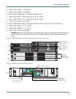


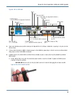
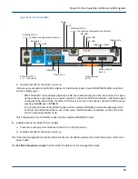


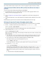


Figure 48. EAC for SMU Nodes
Ethernet NIC 3
eth2
(not used)
SAS port 1
SAS port 2
Reset
Power
OK LED
Ethernet NIC 2
mgmt0
(secondary management network)
Fault LED
Diagnostic LEDs
Local data network (LDN)
port I
Local data network (LDN)
port II
Maint ports
ID LED
Ethernet NIC 4
pub1
(external admin network)
Ethernet NIC 5
pub0
(external admin network)
Ethernet NIC 1
mgmt1
(primary management network)
6. Open a terminal session (with a serial port configured for 115.2 Kbps, 8 data bits, no parity, 1 stop bit, and no
flow control).
7. If the system includes an AMMU, enable power to the AMMU by powering on the 1U servers and their EACs;
then power on the 2U24 EBOD enclosure.
8. Enable power to the 2U24 SMU and the MMU controllers (nodes 1 and 0) that host the MGMT and MGS/
MDS nodes.
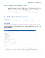
a. At the back of the rack, push the recessed power button on each controller to place both PCM power
switches in the ON position.
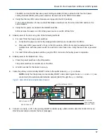
IMPORTANT: Be sure to use the provided reset tool, to avoid damaging the recessed switch.
Figure 49. The OSS Controller Reset Tool
Power On the ClusterStor L300 and L300N System
58


