


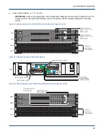


Figure 25. Cable SMU to External Administration Network
A
B
To external
administration
network (EAN)
EAC A Node n000
EAC B Node n001
pub0 interfaces (NIC 5)
SMU
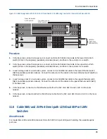
Procedure
1. In the base rack and each expansion rack, connect a QSFP+ data cable to the lower InfiniBand switch (IBS0)
(available ports listed above), and then to the customer core switch.
2. In the base rack and each expansion rack, connect a QSFP+ data cable to the upper InfiniBand switch (IBS1)
(available ports listed above), and then to the customer core switch.
3. In each expansion rack of a multi-rack system, connect a Cat 5/6 Ethernet cable to the lower Ethernet switch
(SW0) (available ports listed above). Connect the other end of the cable to the lower Ethernet switch (SW0) in
the base rack.
4. In each expansion rack of a multi-rack system, connect a Cat 5/6 Ethernet cable to the upper Ethernet switch
(SW1) (available ports listed above). Connect the other end of the cable to the upper Ethernet switch (SW1)
in the base rack.
5. In the base rack, connect a Cat 5/6 Ethernet cable from the NIC card, MGMT node 0, NIC 5 to the local
network.
6. In the base rack, connect another Cat 5/6 Ethernet cable from the NIC card, MGMT Node 1, NIC 5 to the local
network.
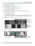
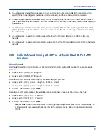
11.3 Cable SMU and 36-Port 40GbE LDN and Dual 24-Port LMN
Switches
About this task
For ClusterStor L300 and L300N inter-rack 40GbE LDN switch cabling, the available uplink ports are:
●
Upper switch 1 (40G1) - all odd-numbered ports
●
Lower switch 0 (40G0) - all odd-numbered ports
For inter-rack LMN switch cabling, the available uplink ports are:
●
Upper switch 1 (SW1) - 5, 7, 17, and 19
Environment Connections
41


