


3
2.0 Hardware Installation and Setup
2-1 Connectors and Indicators
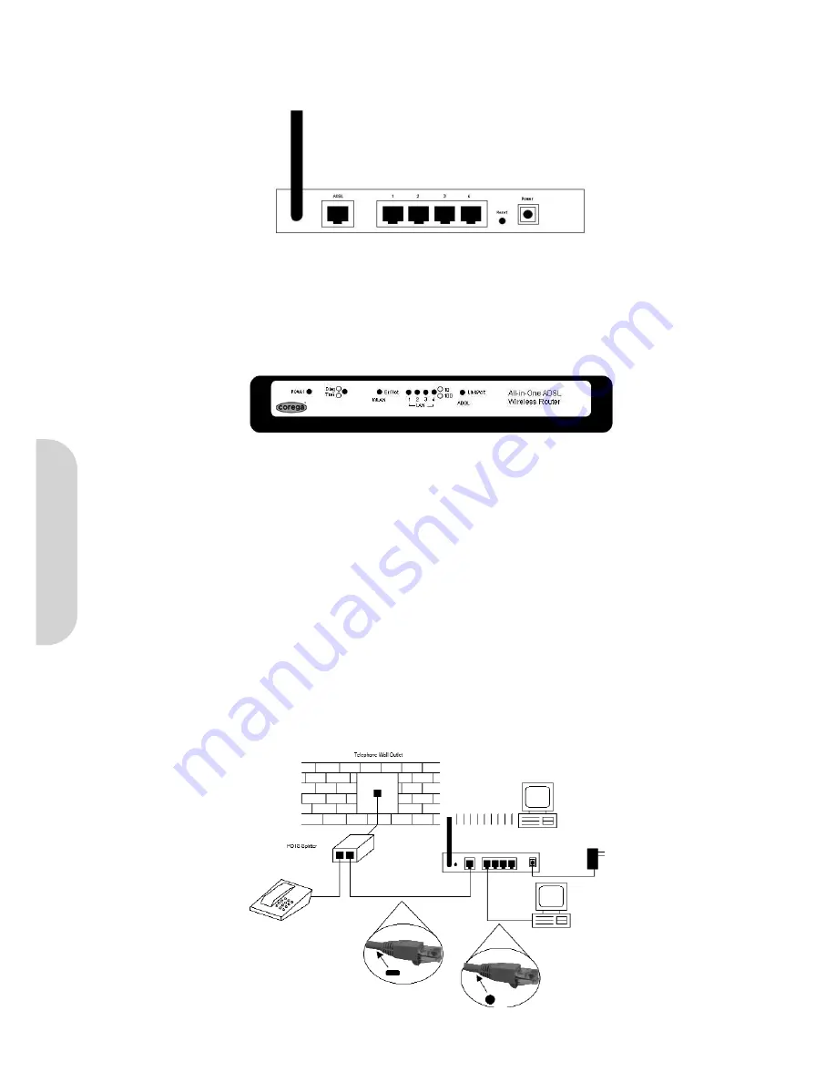
The rear panel of the router is shown in Figure 2.
Figure 2. Rear Panel
• Antenna
Provides data transmission and reception for wireless devices. Please ensure that the Antenna is facing upwards.
• Reset
Pressing this button for 3 seconds will reset the unit back to factory defaults.
• ADSL
This is the WAN connection port to the telephone socket.
• LAN 1–4
Four LAN ports for local computers/printers.
• Power
Inlet socket for external power adapter.
The front panel of the router is shown in Figure 3.
Figure 3. Front Panel
• Power
0ff - No power applied
Green - Power to the router
• Diag/Transaction
Red - Glows when the router performs a self test on power on
Green - On when a link to the ISP is established
• WLAN Enable/Activity
Off - Wireless not enabled
Green - Wireless enabled
Flashing - Data activity on the wireless port
• LAN Link/Activity
Off - Port not active
Green - Port has valid connection
Flashing - Data activity on the port
• ADSL Link/Activity
Off - ADSL line not connected
Green - ADSL connection is established and ready
Flashing - ADSL connection is being established
2-2 Installation
Connect the router as shown.
Figure 4. Hardware Installation
ENGLISH


