


21
4-11 Static Routing
Only users with an excellent understanding of router protocols should attempt to change settings in this area.
The Static Routing feature allows PCs that are connected to the LAN side of the router, to communicate with other PCs that are connected to another router. The router
supports up to 20 route table entries.
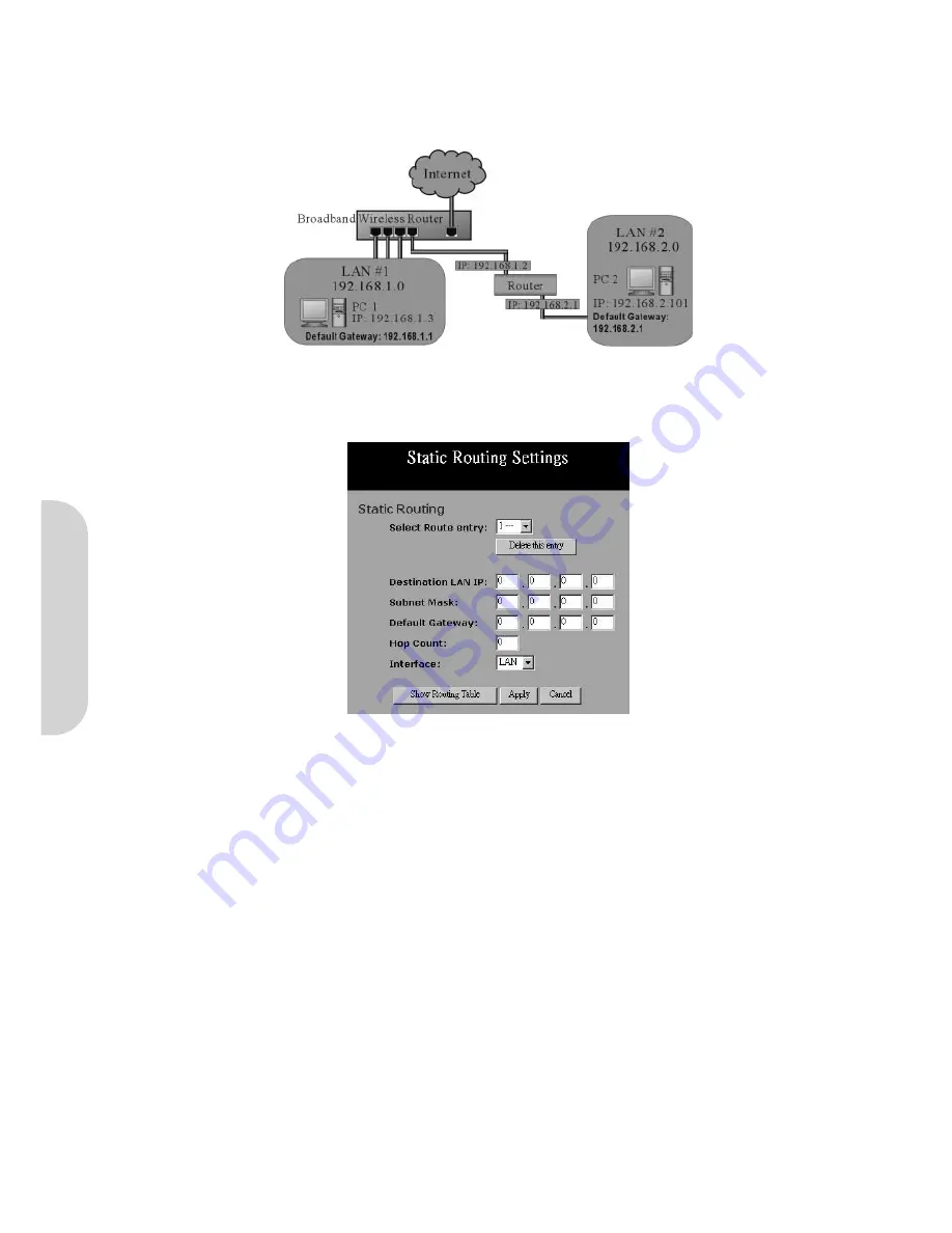
Figure 36. Static Routing Example
In the above diagram, PC2 in LAN#2 is connected to the router via another router while PC1 in LAN#1 is connected to the router directly. Without configuring the Static
Routing function, the two PCs would not be able to communicate with each other.
Figure 37. Static Routing Setting
•
Select Route entry:
Select the route entry number from 1 to 20 that you wish to configure.
•
Destination LAN IP and Subnet Mask:
Enter the IP Address and Subnet Mask of the destination LAN that the immediate LAN is to communicate with. Taking
the above diagram as an example, enter
192.168.2.0
in the “
Destination LAN IP
” field and
255.255.255.0
in the “
Subnet Mask
” field.
•
Default Gateway:
Enter the IP Address of the router that forwards data packets to the destination LAN. For the above example, enter
192.168.1.2
in the
“
Default Gateway
” field.
•
Hop Count:
Enter the number of hops required between the LANs to be connected. The Hop Count represents the “cost” of the routing transmission. The default
value is 1.
•
Interface:
Choose
LAN
if the Destination LAN is on your router’s LAN side and choose
WAN
if the Destination LAN is on the router’s WAN side.
Referring back to the above diagram, with the proper settings, PC1 would be able to access LAN 1, LAN 2 and the internet while PC2 can only access LAN 2, LAN1.
Click the “
Apply
” button after making any changes, or click the “
Cancel
” button to exit the screen without saving any changes.
ENGLISH


