INS_CNGE11FX3TX8MS[POE][HO] Rev. 11.6.17 PAGE 298
INSTRUCTION MANUAL
CNGE11FX3TX8MS[POE][HO]
TECH SUPPORT: 1.888.678.9427
Configuring ERPS from the Web GUI
Initial Switch Configuration
Use the following steps to configure the ERPS features through the Web.
1. Set the proper static IP for each switch. In this example, switch 1 is 192.168.10.1, switch 2 is
192.168.10.2 and switch 3 is 192.168.10.3.
2. Connect switch 1 to switch 2 and switch 1 to switch3. Do not connect switch 2 to switch 3 to
avoid creating a loop. The web client is connected to switch 1.
3. To avoid conflict with ERPS disable spanning tree on all switches if it is enabled.
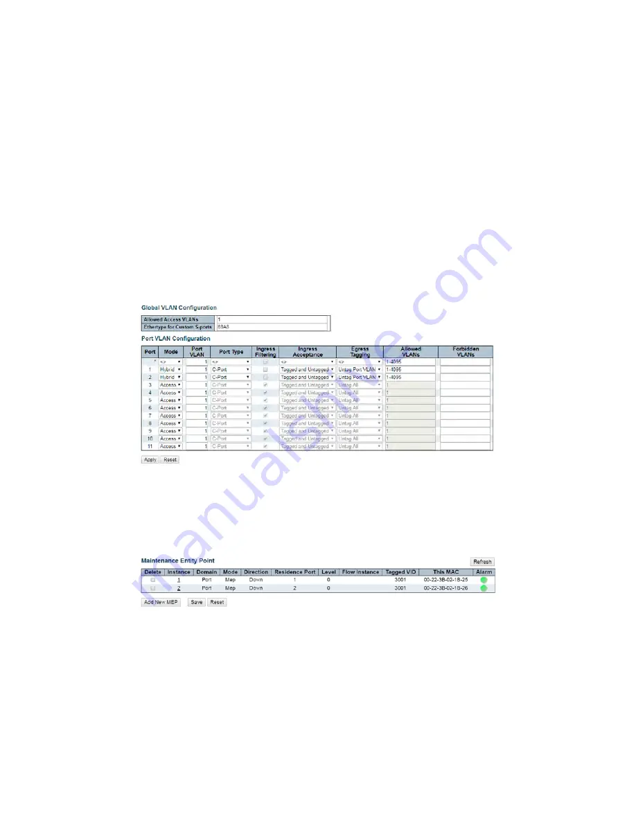
4. Enable VLAN tag aware on all three switches. In VLAN configuration page, set port mode to
Hybrid port and port type to C-Port on port 1 and port 2 for each of the three switches, as
screen shot below.
Figure 1 – Switch 1, 2, & 3 VLAN Configuration
Creating a MEP on Switch 1
1. On switch 1, add a new MEP on port 1 and 2 by clicking MEP. Configure the MEP as shown, and
click Add New MEP.
Figure 2 – Switch 1 Port 1 and 2 MEP Configuration
2. Edit MEP1 by clicking 1 under Instance of the MEP table. Configure the page as shown, and
click Save or Apply.


