


M0201ABK_uc
ERA® WCS and e-POI Subracks and Power Supply Unit Installation Guide
© June 2021 CommScope, Inc.
Page 69
Install and Connect the Subrack Cards
6
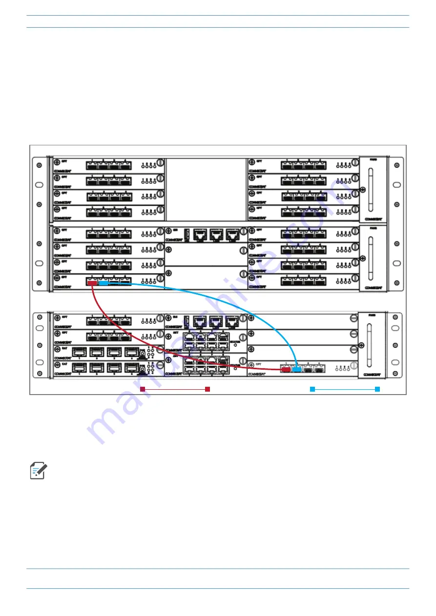
(Optional). To add an additional 320 MHz of RF between the TEN and the Switching CAN, do the following:
a
Obtain a pair of SFP+ Modules that correspond to the length and type of fiber you will use to connect
the CAN to the TEN. Note the maximum range listed in
b
Follow local practice or manufacturer recommendations to clean fiber connectors.
c
Connect one end of the cable with an SFP+ Module into one of the four ports on the OPT Card (labeled
1
-
4
) installed in the Switching CAN.
d
Connect the other end of the cable with an SFP+ Module into
Port
2
on the OPT Card installed in
Slot
R1
of the TEN.
7
(Optional). To add additional TEN-to-CAN links, with each link adding an additional 320 MHz of RF
capacity between the TEN and Switching CAN, follow the process in
, as needed for each additional
link. However, you will now use Ports
R1.2
through
R1.4
, which must be populated consecutively—there
cannot be unused ports between used ports. That is, you cannot use Port
R1.2
and
R1.4
and leave
R1.3
unused.
In addition to the card placement, you must also configure the function of the WCS Subracks in the ERA
GUI. For further information, refer to the ERA configuration guide for Software Version 2.5 or later; see
"Accessing ERA Series User Documentation” on page 83
Main TEN-to-CAN fiber link:
Second TEN-to-CAN fiber link:
WCS-4 Subrack configured as a Switching CAN
WCS-2 Subrack configured as a TEN


