


ERA® WCS and e-POI Subracks and Power Supply Unit Installation Guide
M0201ABK_uc
Page 74
© June 2021 CommScope, Inc.
Install and Connect the Subrack Cards
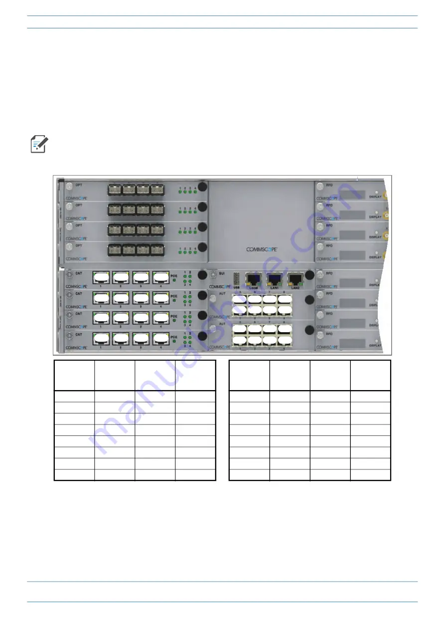
shows the internal mapping between WCS slots and CAT/OPT Card ports to AUT Card slots and
ports. There is a specific relationship between the slot in which the CAT and AUT Cards are installed, and the
CAT and AUT Card ports. For example:
•
The CAT/OPT Card slot/port combination of
L1.1
always maps to AUT Card slot/port combination
M1.1
•
The CAT/OPT Card slot/port combination
L4.4
always maps to AUT Card slot/port combination
M2.8
.
This internal mapping provides the Ethernet backhaul for Ethernet devices connected to the Ethernet ports
on the AUT Card.
Figure 13.
Internal Mapping of CAT/OPT Card Slots and Ports to AUT Card Slots and Ports
Use the preceding information and the following steps to connect the AUT Card(s) to the ERA system.
1
"Install and Connect the Subrack Cards” on page 56
to install the AUT Card(s) into the
WCS Subrack Slots M1 - M2, as needed for this CAT/TEN installation.
2
Use to
as a reference for port assignments of auxiliary devices subtended off an AP.
shows the CAT Card installed in Slots L1 - L4. The mapping shown would be the same for an OPT
Card installed in Slots L1 - L4.
WCS Slot
(L1 - L4)
CAT/OPT
Card Port
AUT Card
Slot
(M1 - M2)
AUT Card
Port
WCS Slot
(L1 - L4)
CAT/OPT
Card Port
AUT Card
Slot
(M1 - M2)
AUT Card
Port
L1
1
M1
1
L3
1
M2
1
L1
2
M1
2
L3
2
M2
2
L1
3
M1
3
L3
3
M2
3
L1
4
M1
4
L3
4
M2
4
L2
1
M1
5
L4
1
M2
5
L2
2
M1
6
L4
2
M2
6
L2
3
M1
7
L4
3
M2
7
L2
4
M1
8
L4
4
M2
8
L1.1
L1.2
L1.3
L1.4
L2.1
L2.2
L2.3
L2.4
L3.1
L3.2
L3.3
L3.4
L4.1
L4.2
L4.3
L4.4
M1.1 M1.2 M1.3 M1.4
M1.5 M1.6 M1.7 M1.8
M2.1 M2.2 M2.3 M2.4
M2.5 M2.6 M2.7 M2.8


