


M0201ABK_uc
ERA® WCS and e-POI Subracks and Power Supply Unit Installation Guide
© June 2021 CommScope, Inc.
Page 63
Install and Connect the Subrack Cards
3
"Install and Connect the Subrack Cards” on page 56
to install the OPT Card into the
WCS Subrack, as needed for this installation:
•
For a Classic CAN, you use:
–
Slots L1 - L4 for an OPT Card connecting a Classic CAN to a TEN or a Fiber AP
–
Slots L1 - L8 for an OPT Card connecting the Classic CAN to a TEN.
•
For a Switching CAN, you use:
–
Slots L1 - L8 for an OPT Card connecting a Switching CAN to a TEN
–
Slots R1 - R8 for an OPT Card connecting a Switching CAN to a WIN.
•
For WINs, you use:
–
Use Port L1.1 to connect to the Switching CAN.
–
Use Ports L1.2 through L2.4 for additional WIN-to-CAN links to increase the WIN bandwidth to
support multiple operators and sectors.
•
For TENs, you use:
–
Slot R1, Port 1 (
R1.1
) to connect to a Classic or Switching CAN.
R1.1
is the primary control slot and
is mandatory.
–
Slot R1, Ports 2 - 4 (
R1.2
-
R1.4
) for additional TEN-to-CAN links.
–
L1 - L4 to connect to a Fiber AP over an optical-fiber link.
4
Use the system design to identify which OPT Card ports will be used in this system.
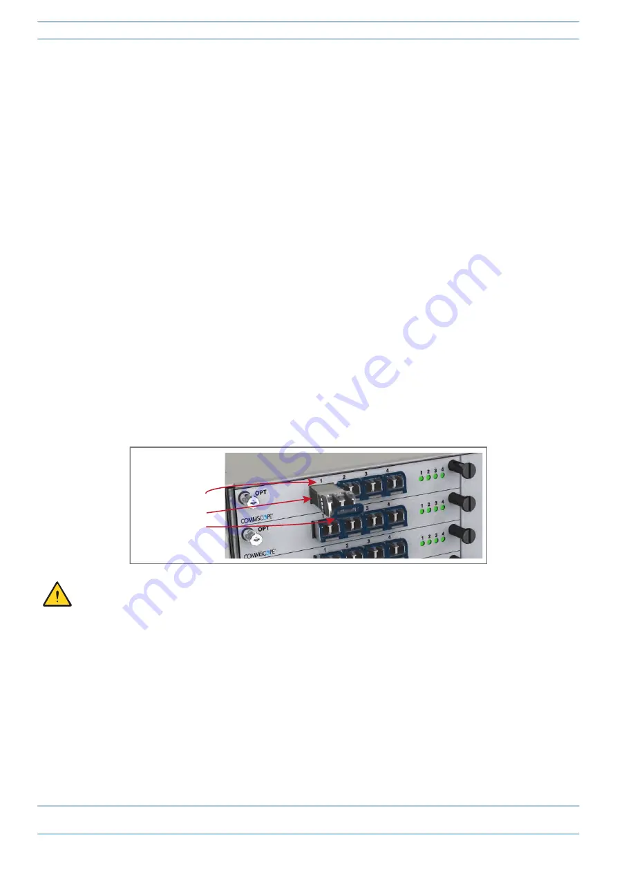
5
Slide the SFP+ into the OPT Card port identified in
, and push the SFP+ into the OPT Card until you
hear it click into place.
Should you need to remove an SFP+ Module, do the following in the order presented to prevent damage
to the SFP+ Module, the OPT Card, or the fiber.
1 Disconnect the fiber cable.
2 Pull the extraction lever on the SFP+ Module towards you. Do not rotate the lever downward more
than 90 degrees to avoid damage to the lever.
3 Use the extraction lever to carefully pull the SFP+ module out of the OPT Card slot.
SFP+ Transceiver
Extracon lever
OPT Card Port 1


