background image

Stand-alone DVR

 Instruction Manual


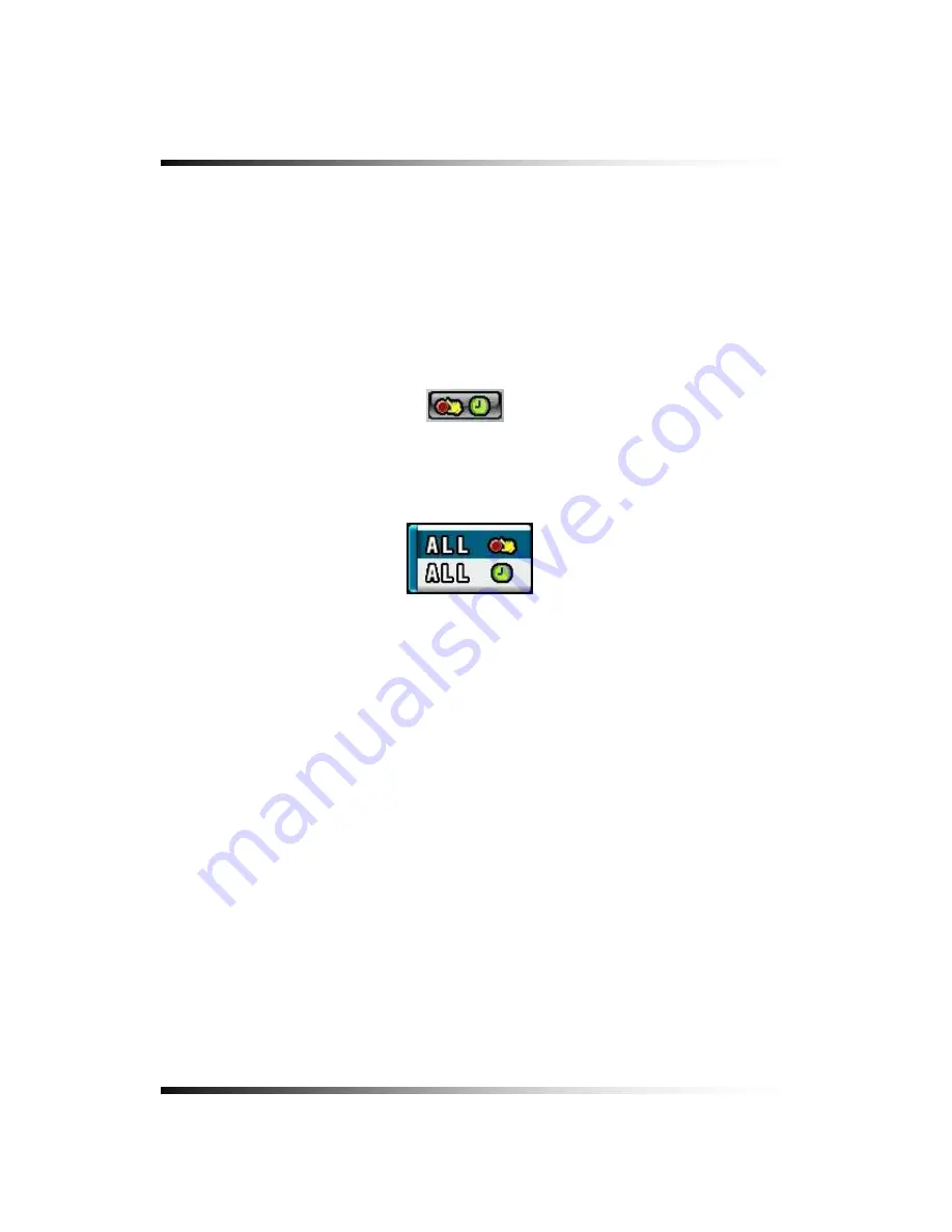
7-6.2. All Manual / Timer recording button 

 Click the 

All Manual / Timer

 recording button in the RECORD menu and the 

All Manual / 

Timer

 recording button will be displayed as shown in Fig.7-57. 

  Select the Manual Recording button or Timer Recording button for all the channels by 

clicking the mouse in Fig.7-57.


  See section 6-8.1 through 6-8.5 

on page 53 through 56

 for more information related to 

recording. 


[Fig.7-56 All Manual / Timer button] 


[Fig. 7-57 All Manual / Timer pop-up window] 


100

Summary of Contents for CDR-0850

Page 1: ...Contents 1 INSTRUCTION MANUAL Stand Alone 8 Channel DIGITAL VIDEO RECORDER MODEL CDR0850 Copyright 2007 Clover Electronics U S A All Rights Reserved ...

Page 2: ...2 ...

Page 3: ...STALLATION 24 5 4 1 Camera Connection 24 5 4 2 Monitor Connection 24 5 4 3 Sensor Connection and RELAY IN OUT 26 5 4 4 RS232C Connection 27 5 4 5 Connection to an Ethernet Optional Network 28 5 4 6 POWER CONNECTION 29 HOW TO OPERATE 31 6 1 GENERAL INFORMATION 33 6 2 OPERATING INTERFACE 34 6 3 IR REMOTE CONTROLLER 35 6 4 POWER ON OFF 36 6 4 1 POWER ON 36 6 4 2 POWER OFF 36 6 4 3 APPEARANCE OR DISAP...

Page 4: ...ording 53 6 8 2 Manual Event Recording 53 6 8 3 Timer Recording 54 6 8 4 Timer Event Recording 55 6 8 5 Recording Icons 56 6 9 REPLAY 57 6 9 1 QUICK REPLAY 57 6 9 2 REPLAY 57 6 9 2 1 Playback Devices 58 6 9 2 2 Set the Start Time 58 6 9 2 3 Replaying 60 6 9 2 4 Disappearance of Replay control buttons 62 6 10 COPY 64 6 10 1 Copying devices 64 6 10 2 Set the Copy Start Time Copying extent 65 6 10 3 ...

Page 5: ...Camera Title 89 7 4 3 Buzzer 90 7 4 4 Relay 90 7 4 5 Pan Tilt Settings 91 7 4 6 Display 95 7 4 7 Sequencing dwell time 95 7 5 AUDIO 96 7 5 1 Camera Channel 97 7 5 2 Audio Recording ON OFF 97 7 5 3 Microphone Volume 98 7 6 RECORD 99 7 6 1 Record ICON Display 99 7 6 2 All Manual Timer recording button 100 7 6 3 All Motion ON OFF Sensitivity and Velocity Setting 101 7 6 4 All Sensors ON OFF 102 7 6 5...

Page 6: ... DYNAMIC DOMAIN NAME SYSTEM 122 7 7 7 HOW TO SETUP AND USE THE DDNS 123 7 7 7 1 Router 123 7 7 7 2 Registration to the DDNS server 124 7 8 VIDEO ENHANCE 125 7 8 1 VIDEO ENHANCEMENT ON EACH CAMERA 126 7 8 2 VIDEO ENHANCEMENT ON VGA OUTPUT 127 REMOTE HOST PROGRAM 129 8 1 REMOTE PROGRAM OVERVIEW 130 8 2 INSTALLING THE PROGRAM TO PC 131 8 3 INTERNET EXPLORER 132 8 4 REMOTE HOST 134 8 4 1 Setup 135 8 4...

Page 7: ...tents 9 2 INSTALLATION OF AN ADDITIONAL HDD 151 APPENDIX 153 RECORDING TIME TABLE 154 FACTORY DEFAULT SETTINGS 155 FAQ 159 I CANNOT LOGIN 160 LIMITED 2YEAR WARRANTY 161 HOW TO OBTAIN FACTORY SERVICE 162 7 ...

Page 8: ...Stand alone DVR Instruction Manual 8 ...

Page 9: ...ow to install and operate the Stand Alone DVR and provides specifications and features Please read this manual thoroughly and follow the installation process before using Stand alone DVR Note Be sure to correctly follow step 3 What to do at the time of installation Contact our dealers when you have any queries 9 ...

Page 10: ...Stand alone DVR Instruction Manual 10 ...

Page 11: ...ng items are included Stand alone DVR unit All Accessories Bracket Power Cable Screws Remote Controller Battery PS2 Mouse DSUB 26p Connector Sensor Input Relay Output Selection Instruction Manual Host Program SmViewer on CD RJ 45 Cable Note Contact your dealer immediately if any components are missing 11 ...

Page 12: ...ve which can be replayed and searched easily any time The CDR0850 supports easy back up via USB port DVD R W CD R W and networking in both static dynamic IP modes User can remotely view live images or search the recorded images Under emergency situation the remote operator can control turn on and turn off the field installed alarms such as a siren or light It is a very user friendly DVR system Use...

Page 13: ...hm Compression The most advanced compression available today Multiple Video Display Support CCTV monitor or TV and High resolution video display by VGA monitor Important Image automatic display by spot monitor Flexible Networking Support TCP IP and Remote Control on all DVR features Up to 10 users can remote access simultaneously Internet Explorer Up to 10 users can remote access simultaneously Ea...

Page 14: ...Stand alone DVR Instruction Manual 14 ...

Page 15: ...PC 2 Connect the cameras the DVR unit and monitor Refer to Fig 5 3 4 Confirm live video is displayed on the monitor before going to the next step 5 Select the Setup Menu and set current date and time Refer to Section 7 2 1 6 Run the FACTORY DEFAULT setting in the SYSTEM menu 7 Perform HDD formatting 8 Escape from Setup Menu 9 Set values for required options 10 Network cable should be connected to ...

Page 16: ...Stand alone DVR Instruction Manual 16 ...

Page 17: ...ooping Main monitor Aux monitor SVHS VGA Composite 1 0 Vp p 75 Ohms 2 times digital Sequence display in Full size 1 screen full Quad pages split 9 split Brightness Contrast control each camera Brightness Contrast saturation 4ch Input 1ch Output 720x480 720x240 360x240 NTSC 720x576 720x288 360x288 PAL Mpeg4 Timer Motion Alarm Manual individually set 0 5 sec 3 IDE HDD Auto overwrite Fast x128 Slow F...

Page 18: ...Stand alone DVR Instruction Manual 18 ...

Page 19: ... NOTE FOR INSTALLATION 22 5 3 SYSTEM CONNECTION 23 5 4 INSTALLATION 24 5 4 1 Camera Connection 24 5 4 2 Monitor Connection 24 5 4 3 Sensor Connection and RELAY IN OUT 26 5 4 4 RS232C Connection 27 5 4 5 Connection to an Ethernet Optional Network 28 5 4 6 POWER CONNECTION 29 19 ...

Page 20: ...nel FULL Screen UP Key c 3 Channel FULL Screen d 4 Channel FULL Screen e 5 Channel FULL Screen LEFT Key f 6 Channel FULL Screen ENTER Key g 7 Channel FULL Screen RIGHT Key h 8 Channel FULL Screen i 9 Channel FULL Screen j 10 Channel FULL Screen DOWN Key k 11 Channel FULL Screen l 12 Channel FULL Screen m 13 Channel FULL Screen n 14 Channel FULL Screen o 15 Channel FULL Screen p 16 Channel FULL Scr...

Page 21: ... b Emergency Record c Zoom d Quick Replay e OSD On Off f Audio g Stop ESC h PTZ z Rear MOUSE RS 422C PORT USB PORT ETHERNET VGA SPEAKER AUDIO INPUT S VHS SENSOR VOLTAGE POWER INLET MAIN VIDEO AUX VIDEO LOOP OUT CAMERA Fig 5 2 Rear View 21 ...

Page 22: ...tilated area and keep minimum of 10 away from obstructions Do not place the unit near heat generating devices Do not place items on top of the unit To secure the product we suggest placing unit in a Wisecomm DVR Lockbox Avoid any area with movement as this can interfere with the internal Hard Drive Use a compatible input output signal type of cameras and monitor Contact your dealer if you are havi...

Page 23: ...5 Installation 5 3 System Connection Fig 5 3 System Connection 23 ...

Page 24: ... switched to impedance status so the external device must have termination resistance 5 4 2 Monitor Connection Connection of Main Monitor Connect the composite monitor to Main on the upper part of BNC connector Connection of Auxiliary Monitor Connect the auxiliary monitor to Aux on the lower part of BNC connector The output of auxiliary monitor port is the same as the main monitor Connection of S ...

Page 25: ...ut for VGA Monitor is the same as that of the main screen however it outputs a better quality signal Pin configuration of VGA Connector Fig 5 5 VGA Connector PIN Number Description Number Description 1 R 75Ω 0 7Vp p 9 N C 2 G 75Ω 0 7Vp p 10 GND 3 B 75Ω 0 7Vp p 11 GND 4 N C 12 N C 5 GND 13 HSYNC 6 GND 14 VSYNC 7 GND 15 N C 8 GND 25 ...

Page 26: ...and support NO Normal Open Refer to Fig 5 6 SENSOR IN OUT PIN for connection Fig 5 6 SENSOR IN OUT PIN RELAY OUT Connection When necessary use RELAY OUT The Output of RELAY OUT is a relay contactor type and supports NO Normal Open NC Normal Close The Output capacity is 220V 1A A higher capacity can cause system failure Refer to Fig 5 7 for the connection to RELAY OUT Fig 5 7 26 ...

Page 27: ... the rear of the unit Specification of the RS232C connector is standard for DSUB9 The Maximum Length of cable is 45 ft When you want to use a longer distance use RS323 to RS422 converter Refer to Fig 5 8 Fig 5 9 Fig 5 10 for connection of Connector PIN Fig 5 8 Fig 5 9 Fig 5 10 27 ...

Page 28: ...n Ethernet Optional Network Connecting the cable to Ethernet Our Ethernet connector is a RJ45 type The maximum cable length is 300 ft When you want to use a longer cable we suggest using repeater Refer to Fig 5 11 for connector pin configuration Fig 5 11 28 ...

Page 29: ...uired voltage Frequent power cuts can cause crucial failures so if you have an unstable power source we recommend the use of an Uninterrupted Power Supply or other backup power source AC Input Voltage is AC110V 50 60Hz or AC220V 50 60Hz AC power Source vary depends on countries Factory default setting is AC110V 50 60Hz Fig 5 12 Input power selection Note Before you input the AC power to the system...

Page 30: ...Stand alone DVR Instruction Manual 30 ...

Page 31: ... 2 OPERATING INTERFACE 34 6 3 IR REMOTE CONTROLLER 35 6 4 POWER ON OFF 36 6 4 1 POWER ON 36 6 4 2 POWER OFF 36 6 4 3 APPEARANCE OR DISAPPEARANCE OF POWER BUTTON 37 6 5 MENU BAR ON OFF 38 6 6 DISPLAY SCREEN 39 6 6 1 FULL SCREEN 39 6 6 2 SPLIT SCREENS 40 31 ...

Page 32: ...Continuous recording 53 6 8 2 Manual Event Recording 53 6 8 3 Timer Recording 54 6 8 4 Timer Event Recording 55 6 8 5 Recording Icons 56 6 9 REPLAY 57 6 9 1 QUICK REPLAY 57 6 9 2 REPLAY 57 6 9 2 1 Playback Devices 58 6 9 2 2 Set the Start Time 58 6 9 2 3 Replaying 60 6 9 2 4 Disappearance of Replay control buttons 62 6 10 COPY 64 6 10 1 Copying devices 64 6 10 2 Set the Copy Start Time Copying ext...

Page 33: ...tionally you can remotely control this unit via RS422C or the Ethernet port located on the back of the unit System status is indicated by either LED lights on the operator buttons or the monitor The system is protected from any accidental pressing of any operator buttons but care should be taken when using the functions of HDD Formatting as this can lead to data loss 33 ...

Page 34: ...ing the buttons on the front panel or buttons on the remote controller and clicking the mouse A lot of users mostly prefer to use a mouse on these kinds of products such as DVRs computers and computer aided devices Therefore we like to describe all the instructions in this manual based on using the mouse 34 ...

Page 35: ...tus 5 Pan Tilt 6 Zoom Focus 7 Search for replaying 8 Up 9 Quit 10 Left 11 Enter 12 Right 13 Quick Replay 14 Down 15 Menu Setup 16 OSD On Off 17 Zoom 18 Freeze IR ID Config 19 No 1 8 Channel Full Screen No 1 16 IR ID Config 1 2 3 5 4 6 7 9 8 11 10 12 14 13 15 16 17 18 19 Fig 6 1 IR Remote Controller 35 ...

Page 36: ...troller Press the POWER button on the front panel for approx 3 seconds until the LED lights are turned off or just press the POWER button on the remote controller and then the following message will be displayed on the screen Fig 6 2Message of POWER off Press the ENTER button to turn the power off By clicking the mouse Click the POWER OFF button on the MENU bar See Fig 6 3 and then the message See...

Page 37: ...bar as shown in Fig 6 3 1 will be disappeared on the screen of the DVR and the client s computer when the system is connected through the SmViewer and the mouse pointer is on the SmViewer See 6 3 2 We designed this function so that users can not turn the power On Off or control the audio functions on the DVR system through internet Fig 6 3 1 Power Audio buttons Fig 6 3 2 No Power Audio buttons To ...

Page 38: ...DVR Instruction Manual 6 5 Menu Bar On Off Right click on the screen in the LIVE or the RECORD mode and the MENU bar will be appeared Right click again and it will be disappeared CLICK CLICK Fig 6 4 LIVE Screen 38 ...

Page 39: ...6 How to Operate 6 6 Display Screen 6 6 1 FULL SCREEN Fig 6 5 FULL screen CAMERA AUDIO COPY CURRENT RECORD SEQUENCE 39 ...

Page 40: ...Stand alone DVR Instruction Manual 6 6 2 SPLIT SCREENS FULL SCREEN SEQUENCING SCREEN 4B 2nd QUAD SCREEN 4A 1st QUAD SCREEN 8 SPLIT SCREEN 40 ...

Page 41: ...CORD mode and a FULL SCREEN will be displayed Click the FULL screen to return to the SPLIT SCREEN 6 7 2 SPLIT SCREEN SPLIT SCREEN is available in the LIVE mode or the RECORD mode Click the DISPLAY icon on the MENU bar and the DISPLAY pop up screen will be displayed See Fig 6 6 Click one of the SPLIT screens on the DISPLAY pop up screen Fig 6 6 DISPLAY pop up screen 41 ...

Page 42: ... will be displayed in sequence and the dwell time can be adjusted in the camera set up menu Refer to 7 4 7 This ICON is displayed on the upper left hand corner of the screen while the system is in the Sequencing Mode Click a Full screen to return to the SPLIT screen while the system is sequencing Fig 6 7 LIVE Menu DISPLAY pop up window Fig 6 8 SEQUENCING screen 42 ...

Page 43: ...L can be changed by clicking the mouse repeatedly Turn the AUDIO speaker ON by clicking the SPEAKER icon as shown below See Fig 6 9 If the ICON turns in red by clicking it represents that the AUDIO is turned OFF and if it turns in yellow it represents that the AUDIO is turned ON Adjust the Audio Volume by Clicking the or the button when the AUDIO is turned ON CHANNEL AUDIO ON Fig 6 9 Audio buttons...

Page 44: ...s clicked in the LIVE mode This function is available on the full screen mode only Click the ZOOM button on the MENU bar in the LIVE mode Move the mouse on the ZOOMED screen and the 8 directional arrow marks will be appeared as shown below Fig 6 10 Click the EXIT button to return to the LIVE Mode Fig 6 10 ZOOMED screen 44 ...

Page 45: ...e Click the OSD button on the MENU bar to turn the OSD On Screen Display ON or OFF When the OSD is in OFF position all the texts on the screen will be disappeared CAM 01 CAM 02 CAM 03 CAM 01 CAM 02 CAM 03 CAM 01 CAM 02 2007 05 25 19 30 41 Fig 6 11 OSD ON SCREEN Fig 6 12 OSD OFF SCREEN 45 ...

Page 46: ...ruction Manual 6 7 7 PAN TILT Click the PAN TILT button on the MENU bar in the LIVE mode to access the PAN TILT cameras Click the EXIT button to return to the LIVE mode Fig 6 13 PAN TILT button Fig 6 14 PAN TILT window 46 ...

Page 47: ... to the LIVE mode press the SPLIT button on the front panel or click the EXIT button ZOOM FOCUS Control the ZOOM and FOCUS of PAN TILT camera Click the ZOOM FOCUS button on the PAN TILT CONTROL window Fig 6 15 PAN TILT CONTROL window or press the UP DOWN LEFT RIGHT button on the front Panel PAN TILT Control the PAN and TILT of PAN TILT camera Click the PAN TILT Button on the PAN TILT CONTROL windo...

Page 48: ... 8 SYSTEM STATUS Click the SYSTEM STATUS button on the MENU bar to see the system status as shown below Fig 6 16 Click the EXIT button to return to the LIVE mode or RECORD mode Fig 6 16 SYSTEM STATUS button Fig 6 17 SYSTEM STATUS window 48 ...

Page 49: ...er is turned OFF Click the POWER LOSS LISTS button on the SYSTEM STATUS window to view the POWER LOSS LISTS Each of the pages contains 10 lists You can search the pages by clicking the UP DOWN button Click the EXIT button to return to the LIVE or RECORD mode Fig 6 18 POWER LOSS LISTS window 49 ...

Page 50: ...AR LISTS button Click the CLEAR LISTS button to clear the lists you will be prompted to confirm changes When you click the OK button the POWER LOSS LISTS will be deleted To cancel click the CANCEL button Fig 6 19 POWER LOSS LISTS Message 50 ...

Page 51: ...gnal is disconnected Click the VIDEO LOSS LISTS button on the SYSTEM STATUS window to view the VIDEO LOSS LISTS Each of the pages contains 4 lists You can search the pages by clicking the UP DOWN button Click the EXIT button to return to the LIVE or RECORD mode Fig 6 20 VIDEO LOSS LISTS window Fig 6 21 VIDEO LOSS window ...

Page 52: ...ISTS button Click the CLEAR LISTS button to clear the lists you will be prompted to confirm changes When you click the OK button the VIDEO LOSS LISTS will be deleted To cancel click the CANCEL button Fig 6 22 VIDEO LOSS LISTS Message window 52 ...

Page 53: ...of the channels can be set by clicking the MANUAL RECORDING on the CAM 1 through CAM 8 The MOTION and SENSOR as shown in Fig 6 23 should be turned OFF in this recording mode Press the RECORD button on the front panel or click the RECORD icon on the MENU bar Fig 6 23 Manual Recording setup 6 8 2 Manual Event Recording Click the SETUP icon on the MENU bar in the LIVE mode Click the RECORD button in ...

Page 54: ...same time by clicking the ALL or each of the channels can be set by clicking the TIMER RECORDING on the CAM 1 through CAM 8 The MOTION and SENSOR as shown in Fig 6 25 should be turned OFF in this recording mode Choose one among WEEKDAY SATURDAY and SUNDAY in the TIMER menu by clicking the mouse on that turns to You can choose the value or by repeatedly clicking the mouse Select the Starting Time a...

Page 55: ...ION and SENSOR as shown in Fig 6 26 should be turned ON in this recording mode Choose one among WEEKDAY SATURDAY and SUNDAY in the TIMER menu by clicking the mouse on that turns to You can choose the value or by repeatedly clicking the mouse Select the Starting Time and Ending Time by clicking the mouse change the values with the mouse s wheel and click the mouse again on the changed values to com...

Page 56: ...per left hand corner of the screen To turn the Recording Icon OFF click the DISPLAY ON in the RECORD menu and then it will be turned OFF You can select the value ON or OFF by repeatedly clicking the mouse Manual Continuous Recording Event Recording Ready MOTION Event Recording SENSOR Event Recording Fig 6 28 Recording Icons 56 ...

Page 57: ...anel or the QICK SEARCH button on the remote controller Press the PLAY button and the recent recorded list will be played 6 9 2 REPLAY Click the REPLAY icon on the MENU bar and the REPLAY window as shown in Fig 6 29 will be displayed Click the EXIT button to return to the previous mode Fig 6 29 REPLAY window 57 ...

Page 58: ... displaying the Ready See Fig 6 30 The corresponding LED will be lit in red when the device is selected Fig 6 30 REPLAY DEVICE button HDD USB CD RW DVD RW 6 9 2 2 Set the Start Time Select the Date year month day on the calendar by clicking the mouse on the highlighted character in black that turns to highlighted character in red See Fig 6 31 The highlighted character in black indicates the dates ...

Page 59: ...play Time set up buttons The time and date can also set on the Replay Time set up button window See Fig 6 33 Select the values year month date and hour minute second by clicking the mouse change the values with the mouse s wheel and click the mouse again on the changed values to complete as shown in Fig 6 33 Fig 6 33 Replay time set up button By using the Replay Time set up bar The starting time t...

Page 60: ...an be possible within a recording time extent Replay buttons NORMAL MOTION SENSOR NORMAL PLAY Click the button to play all the recorded data MOTION PLAY Click the button to play the recorded data by MOTION only SENSOR PLAY Click the button to play the recorded data by SENSOR only 60 ...

Page 61: ...on to pause Click the button to replay when in the pause mode REW FF During replaying press the or button or turn the shuttle ring on the front panel for fast rewinding and fast forwarding up to 128 times Keep pressing the or button to accelerate the speed up to 128 times Same as shuttle ring PREV NEXT During replaying press the button to view previous frame in still image and press 61 ...

Page 62: ...e by clicking the or the button when the AUDIO is turned ON 6 9 2 4 Disappearance of Replay control buttons During replaying the replay control buttons appear on the bottom of the screen To disappear drag the mouse pointer downward until the replay control buttons disappear and to appear drag the mouse pointer upward until the replay control buttons appear 62 ...

Page 63: ...mouse on one out of channels during replaying to view a full screen Click the mouse on the full screen during replaying to return to the split screen Fig 6 36 SPLIT screen during replaying Fig 6 37 FULL screen during replaying 63 ...

Page 64: ...o copy the recorded data plug the USB devices such as external USB HDD USB memory to the USB port or insert a blank media CD R W or DVD R W into the DVD R W drive When the devices and Medias are ready to copy the Ready on the corresponding devices and Medias will be displayed in shown in Fig 6 38 We recommend you to format the USB devices prior to copy the recorded data as follows but the Medias s...

Page 65: ...manufacturer for more information 6 10 2 Set the Copy Start Time Copying extent Select the Date year month day on the calendar by clicking the mouse on the highlighted character in red that turns to highlighted character in black See Fig 6 39 The highlighted character in black indicates the dates and times that recorded data exists and the highlighted character in red indicates the selected dates ...

Page 66: ...start time to copy by clicking the mouse on HOUR 0 23 in the military hour Thereafter the extent of the recording will be saved on Channel selection button Some channels can be selected by clicking the mouse on the corresponding channels By using the Copy Start End set up buttons The time and date can also set on the Copy Start End set up buttons window See Fig 6 41 Select the values year month da...

Page 67: ...e Start End set up bar The starting time to copy can also be set by clicking the slider on the bar and dragging it or just click the bar Fig 6 42 Copy Start End setup bar 6 10 3 Set the Copy End Time Copying extent Refer to the above explanation See section 6 10 2 67 ...

Page 68: ...ouse again on the changed values to complete Select each of channels 1 through 8 in red or A in black for all the channels on the COPY DATA window and click on the SELECTED button to save Fig 6 43 Start Copy Time Setup window To set the ending time and date to copy right click on the replaying screen again and the COPY DATA window that contains end time for copying will be displayed See Fig 6 44 S...

Page 69: ...es and medias will be displayed NETWORK COPY Save the recorded data in PC through the SmViewer by Network Click the Network button on the SmViewer to start copy It is available only on the SmViewer not on the DVR and the networking should be connected to the DVR USB COPY Save the recorded data in USB Device Click the USB Device button to start copy CD RW COPY Save the recorded data on CD R W Media...

Page 70: ...rded data on DVD R W Medias Click the DVD R W button to start copy As soon as one of the above button is clicked copying will start along with displaying the icon shown in Fig 6 45 The following icon indicates that copying is in process Fig 6 45 Copying Icon 70 ...

Page 71: ...76 7 2 2 SYSTEM CONFIG 78 7 2 2 1 FACTORY DEFAULT 78 7 2 2 2 LOAD CONFIG BACKUP CONFIG 79 7 2 3 PASSWORD 82 7 2 4 IR REMOTE ID 83 7 2 5 FIRMWARE UPDATE 84 7 2 6 SYSTEM INFO 84 7 3 DISK MANAGER 85 7 3 1 HDD WRITE FAIL 86 7 3 2 HDD OVERWRITE 86 7 3 3 Format 86 71 ...

Page 72: ...8 7 6 RECORD 99 7 6 1 Record ICON Display 99 7 6 2 All Manual Timer recording button 100 7 6 3 All Motion ON OFF Sensitivity and Velocity Setting 101 7 6 4 All Sensors ON OFF 102 7 6 5 Size Recording Resolution 102 7 6 6 Recording Speed 103 7 6 7 Recording Quality 104 7 6 8 Recording Mode 105 7 6 8 1 Manual Recording 105 7 6 8 2 Manual Event Recording 105 7 6 8 3 Timer Recording Schedule Recording...

Page 73: ...rt Forwarding 119 7 7 4 MAC ID 120 7 7 5 MNS MAC NAME SERVER 120 7 7 6 DDNS DYNAMIC DOMAIN NAME SYSTEM 122 7 7 7 HOW TO SETUP AND USE THE DDNS 123 7 7 7 1 Router 123 7 7 7 2 Registration to the DDNS server 124 7 8 VIDEO ENHANCE 125 7 8 1 VIDEO ENHANCEMENT ON EACH CAMERA 126 7 8 2 VIDEO ENHANCEMENT ON VGA OUTPUT 127 ...

Page 74: ...Setup Icon on MENU bar It is possible to set up the menus in the LIVE mode and partly in the RECORD mode Click the SETUP button on the MENU bar and the SETUP menu will be displayed Click the EXIT button to return to the previous mode Fig 7 2 SETUP menu 74 ...

Page 75: ...7 Setup 7 2 SYSTEM Click the SYSTEM button in the SETUP menu and the SYSTEM menu shown in Fig 7 3 will be displayed Click the EXIT button to return to the SETUP menu Fig 7 3 SYSTEM menu 75 ...

Page 76: ...YSTEM menu Fig 7 4 TIME DATE menu TIME FORMAT Click the mouse on the TIME FORMAT button to change and then select 24 HOUR or 12 HOUR by clicking the mouse Fig 7 5 Time Format button TIME Settings Select the values AM or PM and hour minute second by clicking the mouse change the values with the mouse s wheel and click the mouse again on the changed values to complete Fig 7 6 Time Setting 76 ...

Page 77: ... 7 7Date Format button DATE Settings Select the month date and year by clicking the mouse change the values with the mouse s wheel and click the mouse again on the changed values to complete Fig 7 8 Date Settings button DISPLAY It enables you to display the time and date on the Live screen Click the DISPLAY button to set display on or off Fig 7 9 Display button Note Setting the new time will cause...

Page 78: ...n to return to the SYSTEM menu Fig 7 10 SYSTEM CONFIG 7 2 2 1 FACTORY DEFAULT Click the FACTORY DEFAULT button in the SYSTEM CONFIG menu and you will be asked as shown in Fig 7 12 Fig 7 11 Factory Default button Click the OK button in Fig 7 12 to reset to the Factory Default Values and then the system will save the factory default values settings Click the CANCEL button to cancel 78 ...

Page 79: ...hange the settings to the system LOAD CONFIG This function is to load the changed settings to the system Click the LOAD CONFIG button and the LOAD CONFIG window will be displayed See Fig 7 14 Select a blank file among FILE 1 FILE 2 FILE 3 and FILE 4 by clicking the mouse and click the LOAD button to change the settings See Fig 7 14 Click the CANCEL button to cancel Fig 7 13 LOAD CONFIG button 79 ...

Page 80: ...stem in the near future whenever you change the settings Click the BACKUP CONFIG button and the BACKUP CONFIG window will be displayed See Fig 7 16 Select a blank file among FILE 1 FILE 2 FILE 3 and FILE 4 by clicking the mouse and click the BACKUP button to save the current setting See Fig 7 16 To delete click the mouse on the saved file and click the DELETE button Click the CANCEL button to canc...

Page 81: ...7 Setup Fig 7 16 BACKUP CONFIG window 81 ...

Page 82: ...Click the password button and the On Screen Keyboard will be displayed as shown in Fig 7 17 The factory default password is 11111111 Delete the existing password with the button on the On Screen Keyboard Enter the new password by using the On Screen Keyboard and click on the OK button to save The password should be 8 digits If you executed the factory default setting the existing password will be ...

Page 83: ...e Fig 7 18 IR REMOTE ID button When an IR Remote ID is assigned on the system click the FREEZE button and then on the remote controller click the same channel button as assigned ID on the system to match the IDs between the system and the remote controller When the FREEZE button and the channel button are pressed on the remote controller if the channel button is identical to the assigned ID the DE...

Page 84: ...T button in the SYSTEM menu and the FIRMWARE LIST will be displayed Click on the list and then You will be asked OK or CANCEL Click the OK button to update the firmware and the system will automatically start to reboot Click the CANCEL button to cancel By SmViewer GUI Refer to section 8 4 1 Firmware Update on page136 7 2 6 SYSTEM INFO Click the SYSTEM INFO button in the SYSTEM menu and the SYSTEM ...

Page 85: ... DISK MANAGER window will be displayed See Fig 7 22 Click the EXIT button to return to the SETUP menu A DVD R W and 3 Hard Disk Drives can be installed and all information in regards to the drives will automatically display on the DISK MANAGER window Fig 7 22 DISK MANAGER window 85 ...

Page 86: ...or the OFF If the ON is selected the system continues recording by overwriting start from the first index of the recorded file even though the space of HDD is in full If the OFF is selected the system will stop recording when the space of HDD is in full Fig 7 24 Overwrite button 7 3 3 Format When you install the new Hard Disk Drives HDD it should be formatted before recording Formatting is possibl...

Page 87: ...7 Setup Fig 7 25 HDD FORMAT window 87 ...

Page 88: ...he SETUP menu and the CAMERA menu will be displayed See Fig 7 26 To change the settings in the CAMERA menu stop recording by clicking the RECORD icon on the MENU BAR It is possible only in the LIVE mode Click the EXIT button to return to the SETUP menu Fig 7 26 CAMERA menu 88 ...

Page 89: ... Fig 7 27 Camera ON OFF button 7 4 2 Camera Name Camera Title Click the NAME Camera Title button in the CAMERA menu and the On Screen Keyboard will be displayed as shown in Fig 7 28 Delete the existing NAME Camera Title with the button on the On Screen Keyboard Enter the new NAME up to 8 characters by using the On Screen Keyboard and click on the OK button to save Click on the CANCEL button to can...

Page 90: ...elected the buzzer will sound when video signal lost and if the X is selected the buzzer won t sound Fig 7 29 Buzzer button 7 4 4 Relay The system will automatically activate sirens or other devices through the Relay Outputs on the rear panel when video signal lost Click on each of the channels you wish to select the Relay Outputs among OFF 1 2 3 and 4 Fig 7 30 Relay button Fig 7 31 Relay pop up w...

Page 91: ...k the PAN TILT button on the corresponding channels in the CAMERA menu and the PAN TILT window will be displayed as shown in Fig 7 33 Click the EXIT button to return to the CAMERA menu Fig 7 32 PAN TILT button Fig 7 33 PAN TILT window 91 ...

Page 92: ...he vendor lists will show up Select a vendor on the vendor lists by clicking the mouse Fig 7 34 PAN TILT REMOTE Fig 7 35 PAN TILT Vendor lists Model Click the MODEL button in the PAN TILT window and select the model on the pop up lists by clicking the mouse Fig 7 36 MODEL button Fig 7 37 PAN TILT Model pop up window 92 ...

Page 93: ...57600bps and 115200bps on the Baud Rate pop up window by clicking the mouse Fig 7 38 BAUDRATE button Fig 7 39 Baud Rate pop up window Data Bits Click the DATA BITS button in the PAN TILT window and choose a value among 5 6 7 and 8 on the Data Bits pop up window by clicking the mouse Fig 7 40 DATA BITS button Fig 7 41 Data Bits pop up window 93 ...

Page 94: ... pop up window by clicking the mouse Fig 7 42 STOP BITS button Fig 7 43 Stop Bits pop up window Parity Bit Click the PARITY BITS button in the PAN TILT window and choose a value among NONE ODD EVEN STICK and ZERO on the Parity Bits pop up window by clicking the mouse Fig 7 44 PARITY BIT button Fig 7 45 Parity Bit pop up window 94 ...

Page 95: ...een If the OFF is selected the camera name camera title in the LIVE mode won t be displayed Fig 7 46 Display ON OFF button 7 4 7 Sequencing dwell time Click the SEQUENCING DWELL button in the CAMERA menu and choose a value among 1 2 3 4 and 5seconds on the dwell time pop up window by clicking the mouse Fig 7 47 Sequencing Dwell Time button Fig 7 48 Sequencing Dwell Time pop up window 95 ...

Page 96: ... alone DVR Instruction Manual 7 5 AUDIO Click on the AUDIO button in the SETUP menu and the AUDIO menu will be displayed on the screen Click the EXIT button to return to the SETUP menu Fig 7 49 AUDIO menu 96 ...

Page 97: ...50 Camera Channel button Fig 7 51 Camera Channel pop up window 7 5 2 Audio Recording ON OFF Click the REC audio recording button in the AUDIO menu and select the O or X by clicking the mouse If the O is selected the corresponding channel s audio will record along with video signal If the X is selected the corresponding channel s audio won t record but video signal will record continuously Fig 7 52...

Page 98: ...Stand alone DVR Instruction Manual 7 5 3 Microphone Volume Adjust audio volume by clicking the or button Fig 7 53 Microphone Volume control button 98 ...

Page 99: ...UP menu Fig 7 54 RECORD menu 7 6 1 Record ICON Display The Recording Icons depends on recording modes are displayed on the upper left corner of the screen To turn the Recording Icon OFF click the DISPLAY ON in the RECORD menu and then it will be turned OFF You can select the value ON or OFF by repeatedly clicking the mouse Fig 7 55 Record ICON Display button 99 ...

Page 100: ...ual Timer recording button will be displayed as shown in Fig 7 57 Select the Manual Recording button or Timer Recording button for all the channels by clicking the mouse in Fig 7 57 See section 6 8 1 through 6 8 5 on page 53 through 56 for more information related to recording Fig 7 56 All Manual Timer button Fig 7 57 All Manual Timer pop up window 100 ...

Page 101: ...ding by motion detection for all the channels By clicking the mouse select the on the pop up window See Fig 7 59 and choose one of the sensitivity among LOW 1 2 3 and HIGH for all the channels with the mouse s wheel and then click it to save By clicking the mouse select the on the pop up window See Fig 7 59 and choose one of the velocity among LOW 1 2 3 and HIGH with the mouse s wheel and then cli...

Page 102: ...nsor Passive Infrared sensor for all the channels Fig 7 61 All Sensor Setup button Fig 7 62 All Sensor Setup pop up window 7 6 5 Size Recording Resolution Select the size of the screen for recording The larger the size selected the better display quality is but the larger the data becomes Click the SIZE Recording Resolution button on each of the channels in the RECORD menu and the SIZE Recording R...

Page 103: ...layed as shown in Fig 7 66 Select one of the Recording Speed among AUTO 30 15 10 7 5 3 2 1 and OFF on the pop up window by clicking the mouse If the AUTO is selected on all the channels the Recording Speed on all the channels should be the same If the OFF is selected the corresponding channel won t be recording Fig 7 65 Record Speed button Fig 7 66 Record Speed pop up window 103 ...

Page 104: ... Recording Quality Click the QUALITY button on each of the channels in the RECORD menu and the QUALITY pop up window will be displayed as shown in Fig 7 69 Select one of the Recording Quality among LOW NORMAL HIGH and BEST on the pop up window by clicking the mouse Fig 7 68 Record Quality button Fig 7 69 Record Quality pop up window 104 ...

Page 105: ... only one of the most popular Recording modes for users but also one of the most convenient Recording modes to use Users can select one of the following Recording modes depends on their application 7 6 8 1 Manual Recording See section 6 8 1 on page 53 7 6 8 2 Manual Event Recording See section 6 8 2 on page 53 7 6 8 3 Timer Recording Schedule Recording See section 6 8 3 on page 54 7 6 8 4 Timer Ev...

Page 106: ...bar should be selected in this recording mode If not it won t be recording Click the mouse on the button for each of the channels in the RECORD menu and the MOTION menu will be displayed on the screen as shown in Fig 7 70 Click the EXIT button to return to the RECORD menu Fig 7 70 MOTION menu ON OFF The system will start to record when MOTION is detected and the ON is selected in the MOTION menu b...

Page 107: ...e mouse s wheel and then click it to save Fig 7 72 Pre Record Time setup button Fig 7 73 Pre Alarm Time Setup pop up window Motion Hold Time Setup The system continues recording for the MOTION HOLD TIME and finishes the recording Click the mouse on the HOLD in the MOTION menu and choose one of the values among 1 through 30 seconds with the mouse s wheel and then click it to save Fig 7 74 Hold Reco...

Page 108: ...tection Area displays in blue on the screen and it turns to yellow color when the motion is detected The white color on the screen represents none of detection area There are three kinds of REGION settings as follows By All Set Click the ALL SET button in the MOTION menu on each of the cameras and the Motion Detection Area displays in blue on the screen as shown in Fig 7 77 Right click on the blue...

Page 109: ...in the MOTION menu in order to clear the Motion Detection Area and the window turns to white color as shown in Fig 7 79 Right click on the current window to return to the MOTION menu Fig 7 78 ALL CLEAR button CURSOR Fig 7 79 All Cleared screen 109 ...

Page 110: ...uld like to designate and then click the other one of cells for the ending point of area until the motion detection area is the size you want it to be The multiple motion areas can be set on each of cameras The motion detection by Window Set will be made on the designated area only Right click on the current window to return to the MOTION menu Fig 7 80 WINDOW SET button CURSOR Fig 7 81 Window Set ...

Page 111: ...ready created the motion detection area will be displayed Click the starting point and the ending point as much as you wish to clear or it can be cleared by ALL CLEAR as described above See ALL CLEAR Right click on the current window to return to the MOTION menu Fig 7 82 WINDOW CLEAR button CURSOR Fig 7 83 Window Clear setup screen 111 ...

Page 112: ...on each of the cameras and click the mouse on each of the cells as much as you would like to designate the Motion Detection Area To clear click the designated cells Right click on the current window to return to the MOTION menu Fig 7 84 EACH CELL button CURSOR Fig 7 85 Each Cell Setup screen 112 ...

Page 113: ...el and motion area to fit your requirements Do not use this function in an area where many objects are continuously moving In case of this change the recording mode to the Continuous Manual Recording mode Use a high quality camera that does not generate video static or noise The motion detection algorithm recognizes this noise as a motion and records the noise even if there was no actual motion Do...

Page 114: ...on the screen as shown in Fig 7 88 Click the EXIT button to return to the RECORD menu Fig 7 88 SENSOR window ON OFF The system will start to record when Alarm is detected and the ON is selected in the SENSOR menu by clicking the mouse If the OFF is selected the system won t be recording If you select OK it will be recorded when only sensor is detected Fig 7 89 SENSOR ON OFF button 114 ...

Page 115: ...just prior to Sensor activation Click the mouse on the PRE in the SENSOR menu and choose one of the values among 0 1 2 3 4 and 5 seconds with the mouse s wheel and then click it to save Fig 7 90 Pre Alarm Time Setup button Fig 7 91 Pre Alarm Time Setup pop up window 115 ...

Page 116: ... one of the values among 1 through 30 seconds with the mouse s wheel and then click it to save Fig 7 92 Alarm Hold Time Setup button Spot Setup If the ON is selected by clicking the mouse on the SPOT button in the SENSOR menu a full screen will display when a motion is detected If the OFF is selected the full screen won t be displayed even though alarm is detected Fig 7 93 Spot Setup button 116 ...

Page 117: ...enu DYNAMIC IP automatically receives IP address from the router or gateway With Dynamic IP It doesn t need to enter the GATEWAY ADDRESS SUBNET MASK IP ADDRESS STATIC IP requires you to enter the GATEWAY ADDRESS SUBNET MASK IP ADDRESS Click the IP MODE button in the NETWORK menu and the IP mode pop up window will be displayed on the screen See Fig 7 96 Select the STATIC or DYNAMIC by clicking the ...

Page 118: ... IP ADDRESS button in the STATIC IP MODE and the On Screen Keyboard will appear Delete the current values with the button and enter the address numbers by using On Screen Keyboard and then click OK button to set with new address Click the CANCEL button to return to the original values Fig 7 97 Address Setup window Fig 7 98 On Screen Keyboard 118 ...

Page 119: ...the new port number by using On Screen Keyboard and then click OK button to set with new port number Click the CANCEL button to return to the default value Fig 7 99 Port Setup window Fig 7 100 Port Setup Keyboard window 7 7 3 1 Port Forwarding Router has to be set as a virtual server or port forwarding in order to utilize the MNS Mac Name Server or the DDNS service to use Internet Explorer See sec...

Page 120: ...erate the other one will automatically start to work Click the MNS button in the NETWORK menu with a mouse buttons on the front panel or remote controller and then the MNS window will show up as below See Fig 7 101 To return to the NETWORK window click the EXIT button in the MNS menu Fig 7 101 MNS window DISABLE ENABLE You can select the DISABLE or ENABLE button on both SERVER 1 and SERVER 2 by cl...

Page 121: ... of the important factors to access the DVR through MNS MAC NAME SERVER with the SmViewer GUI Click the SITE NAME button the On Screen Keyboard will show up See Fig 7 104 Delete the current SITE NAME with the button and enter the new SITE NAME by using the On Screen Keyboard pressing the buttons on the front panel or remote controller and then click OK button to save it Click the CANCEL button to ...

Page 122: ...exit by clicking the mouse Choose the SERVER button in the DDNS menu by clicking the mouse and select the DESABLE and then click the EXIT button SERVER the SERVER button in the DDNS menu by clicking the mouse pressing the by Fig 7 105 DDNS menu Choose buttons on the front panel or remote controller and select the DYNDNS ORG provided www dyndns org at no cost ST NAME in the DDNS menu and enter the ...

Page 123: ...he OK button Fig 7 108 USER ID button Click the PA to the DDNS service provider by using the On Screen Keyboard After changing the values click on the OK button Fig 7 109 PASSWORD button 7 7 7 7 1 Router It has to be se a lot of manufacturers on the market Please read the provided manual thoroughly before setting or visit our website at www cloverusa com in regards to do it We the manufacturer of ...

Page 124: ...o www dyndns com and log in with the ID and the Password 5 After log in on dyndns com front page click on my services 6 Click on the Add Host Service Next to Host Level Service 7 Click the Add Dynamic DNS Host on the Dynamic DNS 8 The window to input Host Name will pop up and select the dyndns org or the 9 ton on the bottom R and enter the HOST ee dvrdns org on the pop up window To complete click ...

Page 125: ...n in the SETUP menu to enhance the picture quality on each of channels and VGA OUTPUT such as Brightness Contrast and Saturation The VIDEO ENHANCE menu will show up See Fig 7 110 To return to the SETUP menu click the EXIT button Fig 7 110 VIDEO ENHANCE 125 ...

Page 126: ...T button in the VIDEO ENHANCE menu The CONTRAST and BRIGHTNESS sliders will be displayed along with camera picture as shown in Fig 7 111 Adjust Contrast and Brightness with the sliders by clicking the mouse To return to the VIDEO ENHANCE menu Click the EXIT button Fig 7 111 CAMERA INPUT 126 ...

Page 127: ...he VIDEO ENHANCE menu The CONTRAST BRIGHTNESS and SATURATION sliders will be displayed along with camera picture Adjust Contrast Brightness and saturation with the sliders by clicking the mouse To return to the VIDEO ENHANCE menu Click the EXIT button Fig 7 112 VGA OUTPUT 127 ...

Page 128: ...Stand alone DVR Instruction Manual 128 ...

Page 129: ...GRAM OVERVIEW 130 8 2 INSTALLING THE PROGRAM TO PC 131 8 3 INTERNET EXPLORER 132 8 4 REMOTE HOST 134 8 4 1 Setup 135 8 4 2 Connection 137 8 4 3 Switch the Normal Screen to Full Screen 138 8 4 4 Speaker Microphone 139 8 4 5 Copy 140 8 5 PLAYER 142 129 ...

Page 130: ...up at any time In order to log in to the DVR system users should be requested to enter the password if the password is already turned ON in the SYSTEM menu Click SETUP SYSTEM This ensures that only authorized personnel are allowed to log in Remote system minimum requirements Microsoft Windows 2000 or XP Operating System Pentium 4 2 0GHz or higher 256MB System memory 1024 x 768 Display Resolution 3...

Page 131: ...tup EXE The software installation will begin 5 After the installation has been completed the SmViewer icon will be created on your desktop screen as shown below 7 Double click the SmViewer icon and the SmViewer screen appears Fig 8 1 SmViewer icon How to set Screen Resolution and Color Quality 1 Click Start point to Control Panel and then click on it 2 Double click Display icon 3 In Display Proper...

Page 132: ... How to setup the Internet Explorer Registration to the www dyndns org See section 7 7 6 on page 122 In the IP address box of Microsoft Internet Explorer type the HOSET NAME See Fig 8 2 you entered in the DDNS menu and the PORT NUMBER of the DVR and then you will be asked to install the AciveX control software See Fig 8 3 You should type the protocol http the host name example cloverdvr1 dyndns or...

Page 133: ...een and the following window will be displayed Fig 8 4 Install the SmViewer Click on the Install button on the above window See Fig 8 4 and the SmViewer will be shown Refer to the following pages in regards to the SmViewer Note We have been developing the new software in order to access the remote DVR systems via the web browser It will be uploaded to www cloverddns com after finalizing Please vis...

Page 134: ...ne DVR Instruction Manual 8 4 Remote Host Fig 8 5 SmViewer 134 Buttons of Remote Host Program Player button Connection button Setup Config button Full Screen button Speaker Microphone volume control EXIT button ...

Page 135: ...the Quick Copy and the Live Copy Quick Copy Click on the Quick Copy for faster copying the recorded data from the DVR to the Host Program SmViewer without live images The copying speed of the Quick Copy is faster than the Live Copy Live Copy Click on the Live Copy for copying the recorded data from the DVR to the Host Program SmViewer with live images The copying speed of the Live Copy is lower th...

Page 136: ...te Save the latest Firmware to the System Files Open Windows Explorer click My Computer click the Program Files click StandAlone MPEG4 DVR click System Files Click the Firmware Update button on the Fig 8 6 and you will be asked Do you want to update a firmware Click the Yes to update Double click the latest firmware as shown in Fig 8 7 and then you will be asked Shall I update firmware Click the O...

Page 137: ... a Site Name in the Name Lists and then click the CONNECT button In order to access the DVR With Get Server setting Click the CONNECT button on the SmViewer and the SmViewer will be displayed Click the mouse on the Get Server in the Connect Dialog menu and click the EDIT button and enter the IP address Port number and Site Name which must be the same as DVR has SETUP click NETWORK click MNS in the...

Page 138: ...en Click the FULL SCREEN button on the SmViewer and the current screen size will be enlarged to fit the monitor s screen size but the resolution will be lowered Click the FULL SCREEN button again to go back to the NORMAL SCREEN Fig 8 9 Switch the Normal Screen to Full Screen 138 ...

Page 139: ...rn the Speaker ON or OFF by clicking the mouse PC Microphone ON OFF Turn the Microphone ON or OFF by clicking the mouse PC Speaker Volume Control Adjust the Speaker Volume by clicking the amount of audio volume It is available when the Speaker is turned ON Microphone Volume Control Adjust the Microphone Volume by clicking the amount of audio volume It is available when the Microphone is turned ON ...

Page 140: ...rded data to client computer with these icons Click the COPY button on the menu bar and the COPY menu will be displayed on the screen In order to set the Copy starting time and the Copy ending time select the values year month date and hour minute second by clicking the mouse change the values with the mouse s wheel and click the mouse again on the changed values to complete Click the mouse on the...

Page 141: ...8 Remote Host Program Fig 8 12 Copying on the SmViwer Fig 8 13 Copy Completion 141 ...

Page 142: ...utton of Player Program Status window Play mode Date Time Calendar Convert to AVI File Search button for replaying Capture button Print button Division button Playback Replay speed Control Search slider for replaying Replay Control Volume Control Exit program button 142 ...

Page 143: ...button on the Player and the Convert AVI window will be displayed See Fig 8 17 Click on the SELECT button on the Convert AVI window and the Browse for Folder will be displayed See Fig 8 18 and Fig 8 19 Select the folder that contains the recorded data and select one of the channels by clicking the mouse and click the OK See Fig 8 20 Click the Start Convert button on the Convert AVI window and clic...

Page 144: ...Stand alone DVR Instruction Manual Fig 8 17 Convert AVI window Fig 8 18 Backup Files by Networking Fig 8 19 DvrRecData by USB 144 ...

Page 145: ...ay the AVI files By using Windows media player Click the OPEN button on the Convert AVI window and double click one of the AVI files to play The AVI files will save in the AVI Files folder Open Windows Explorer click My Computer click the Program Files click StandAlone MPEG4 DVR click AVI Files 145 ...

Page 146: ... button when a full screen is replaying on the Player and the current images will be saved in the Printed Files Open Windows Explorer click My Computer click the Program Files click StandAlone MPEG4 DVR click Printed Files in JPEG file format Print button Click the Print button when a full screen is replaying on the Player and the current images will print out along with comments if you write down...

Page 147: ...ons while replaying Full Screen 4 Division Screen 9 Division Screen 16 Division Screen Fig 8 24 Division button Playback Replay Speed Control Move the slider with the mouse to control the replaying speed The 0 represents the normal speed and represents slow speed and fast speed respectively Fig 8 25 Replay Speed Control Slider ...

Page 148: ...t or just click the bar to search the recorded data Fig 8 26 Replay Search Slider Replay Control Refer to section 6 9 2 3 FF STOP NEXT REW PREV PLAY Fig 8 27 Replay Control buttons Volume Control Control the volume when replaying on the full screen mode Fig 8 28 Replay Volume Control Slider Exit button Click the Exit button on the Player to exit 148 ...

Page 149: ...9 Installation of additional HDDs CONTENTS 9 1 HDD HARD DISK DRIVE INSTALLATION 150 9 2 INSTALLATION OF AN ADDITIONAL HDD 151 149 ...

Page 150: ... manufacturer already installed a 320GB of Hard Disk Drive IDE and a DVD R W To install additional hard disk drives refer to the following pages Note Jumper settings for all the Hard Disk Drives and the DVD R W should be made on Cable Select Do not set the jumper settings as Master or Slave on any of IDE Drives the system won t be working properly Fig 9 1 System in 150 ...

Page 151: ... and remove the cover Install the additional HDD in the space as shown in Fig 9 1 Connect the power connector and the flat cable to the HDD Reassemble the cover Turn on the system and confirm that the system recognizes the additional HDD If the system fails to recognize the HDD check the correct jumper settings and secure cable connections Note After installing the additional HDD formatting on the...

Page 152: ...Stand alone DVR Instruction Manual 152 ...

Page 153: ...APPENDIX CONTENTS RECORDING TIME TABLE 154 FACTORY DEFAULT SETTINGS 155 153 ...

Page 154: ...0 HIGH 232 00 348 00 497 00 696 00 1160 00 1741 00 3481 00 NORMAL 541 00 812 00 1160 00 1624 00 2706 00 4059 00 8119 00 LOW 1098 00 1647 00 2353 00 3294 00 5491 00 8236 00 16472 00 DAYS Each Total 15 fps 120fps 10 fps 80fps 7 fps 56fps 5 fps 40fps 3 fps 24fps 2 fps 16fps 1 fps 8fps BEST 2 90 4 30 6 20 8 70 14 50 21 70 43 40 HIGH 9 70 14 500 20 70 29 000 48 30 72 50 145 00 NORMAL 22 60 33 80 48 30 ...

Page 155: ...DATE FORMAT YYYY MM DD 3 LOAD BACKUP CONFIG NONE LISTS 4 USER ACCOUNT PASSWORD SET YOUR PASSWORD THE PASSWORD IS NULL PASSWORD ON OFF OFF 5 IR REMOTE ID OFF 6 HDD OVERWRITE ON 7 CAMERA ACTIVE ALL ON NAME CAM XX BUZZER ALL ON RELAY ALL OFF PAN TILT VENDOR PELCO DISPLAY ON SEQ DISPLAY DWELL 1 SEC 155 ...

Page 156: ...3 RECORD OFF MIC 5 AUDIO 4 RELATED CAMERA CH 4 RECORD OFF MIC 5 9 RECORD RECORD ICON DISPLAY ON SIZE ALL HALF D1 704 X 240 FPS ALL 15 fps QUALITY ALL HIGH MODE ALL MANUAL RECORD MODE SENSITIVITY LOW 19 TIMER RECORD ACTIVE ALL OFF TIMER ALL 00 00 MOTION DETECT OFF PRE 1 sec HOLD 1 sec SPOT OFF REGION ALL SET SENSOR DETECT OFF PRE 1 sec HOLD 1 sec SPOT OFF 156 ...

Page 157: ...60 84 25 SERVER 1 PORT 300 SERVER 2 MODE DISABLE SERVER 2 IP ADDRESS 221 149 149 117 SERVER 2 PORT 300 SERVER SITE NAME SXXXXXX MAC ADDRESS 11 VIDEO CAMERA INPUT BRIGHTNESS 128 Max 255 CONTRAST 128 Max 255 VGA OUTPUT BRIGHTNESS 20 Max 40 CONTRAST 20 Max 40 SATURATION 20 Max 40 157 ...

Page 158: ...Stand alone DVR Instruction Manual 158 ...

Page 159: ...FAQ CONTENTS I CANNOT LOGIN 160 159 ...

Page 160: ...x xxx xxx is the DVR IP Request timed out Check IP address Reply from xxx xxx xxx xxx Check Port number Check if other user is using this Please check the Port number of DVR and PC is identical Check Port number at MENU SETUP SYSTEM NETWORK IP CONFIG PORT 5800 on DVR TARGET PORT NUMBER 5800 on Host Program Please confirm the Password of DVR and PC is identical Check Password at MENU SETUP SYSTEM P...

Page 161: ...r products do not function because of any defect in material or workmanship we will repair it for free for 2 year on parts and labor from the date of original purchase This warranty does not cover modification abuse incidental or consequential damages unless the state of owner s residence specially prohibits limitations on incidental or consequential damages 161 ...

Page 162: ... limited warranty z Please pack the system carefully and securely using the original packing materials and send it prepaid and insured to 13073 E 166th St Cerritos CA 90703 Please include a check for 40 00 to cover the cost of return postage and handling If the system is returned within the warranty period please include a proof of purchase If the system is out of warranty you will receive an esti...

Reviews: