Chromasens GmbH - Max-Stromeyer-Straße 116 - 78467 Konstanz
– Germany
www.chromasens.de
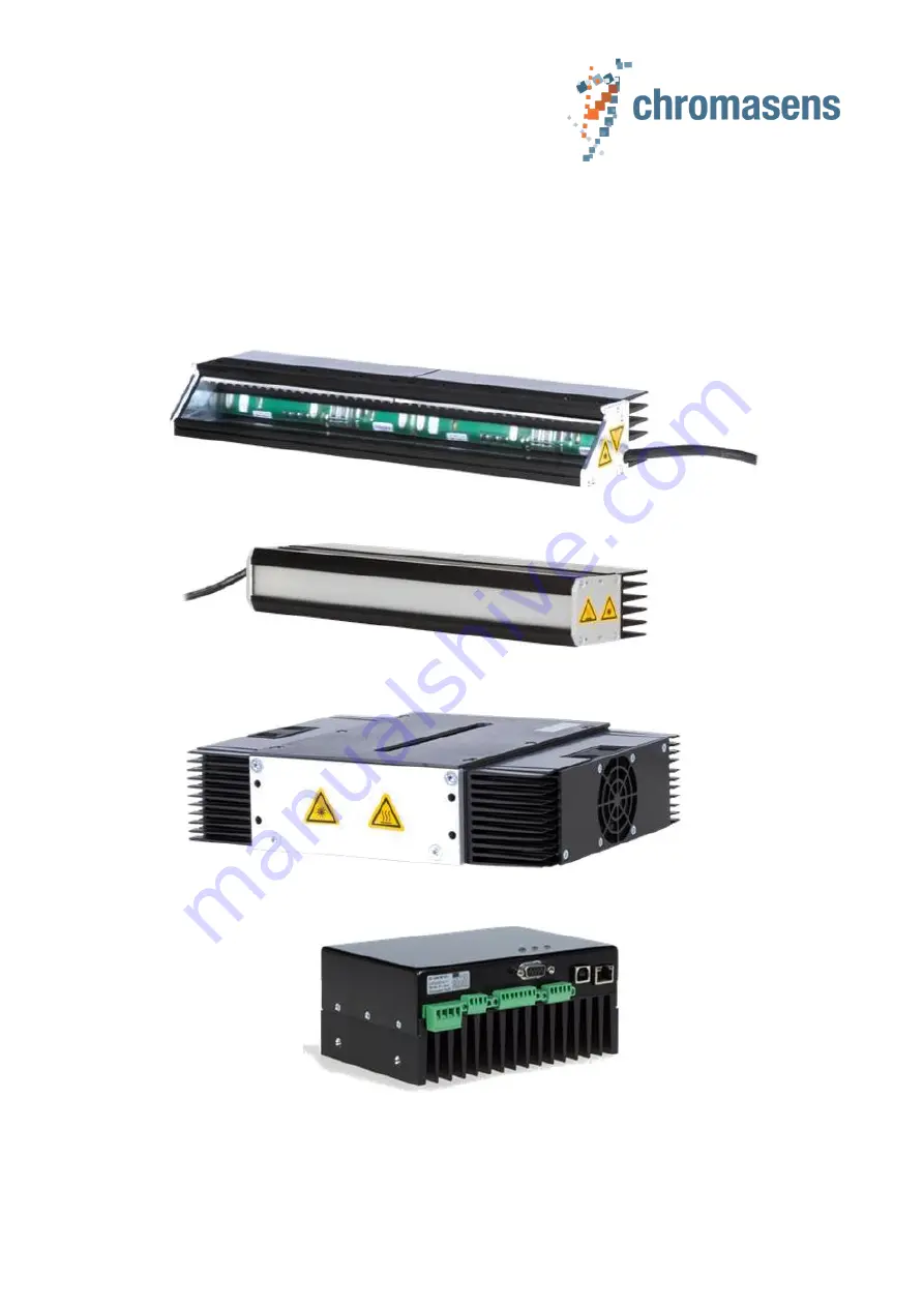
Corona II + LED-Control Unit XLC4-1
Manual
Version R05
(CD40069)
07/2020
Page 1: ...Chromasens GmbH Max Stromeyer Straße 116 78467 Konstanz Germany www chromasens de Corona II LED Control Unit XLC4 1 Manual Version R05 CD40069 07 2020 ...
Page 2: ... transport 17 5 LED Module Corona II 18 5 1 Configuration 18 5 1 1 Breakdown of an identification number 18 5 1 2 Options with identification number 19 5 1 2 1 Special options 24 5 2 Optical length Fitting length ID 1 25 5 2 1 Mechanical dimensions 25 5 2 2 Number of channels per module 31 5 2 3 Mounting Corona II with length 680 mm 31 5 2 4 Cabling and operating Corona II with length 680 mm 32 5 ...
Page 3: ...ED 59 5 4 6 2 Relative spectral emission of IR940 nm LED 59 5 4 6 3 Relative radiant flux of IR940 nm LED 60 5 4 7 Standard light color D50 ID 3 07 and 10 61 5 4 7 1 Relative spectral emission of D50 light color 61 5 4 8 UV 395 nm and 365 nm ID 3 33 or 30 62 5 4 8 1 Spectral characteristics of UV 395 nm LED 62 5 4 8 2 Relative spectral emission of UV 395 nm LED 62 5 4 8 3 Spectral characteristics ...
Page 4: ...onality 87 6 5 1 Power up 87 6 5 2 Commands 88 6 5 2 1 Code sampe in C 88 6 5 2 2 General structure of all commands 89 6 5 2 3 Command VR request firmware version and release 90 6 5 2 4 Command IF request hardware info of controller unit 91 6 5 2 5 Command TE query temperatures 93 6 5 2 6 Command LC switch LED 94 6 5 2 7 Command IY set channel current 95 6 5 2 8 Command ID set device ID 97 6 5 2 9...
Page 5: ...ing an XLC4 controller 125 7 3 1 Connecting the XLC4 controller to the XLC4 commander 125 7 3 1 1 RS232 USB RS485 125 7 3 1 2 Ethernet 126 7 3 2 Disconnect the XLC4 controller from the XLC4 commander 127 7 3 3 Connecting and disconnecting several XLC4 controllers 127 7 3 4 Status of connections 127 7 3 5 Control panel for Corona modules 128 7 3 6 Operating the Corona with the XLC4 commander 129 7 ...
Page 6: ...9 8 4 4 Example 150 8 5 Operating the D50 Corona 151 8 5 1 Requirements 151 8 5 2 Connection 151 8 5 3 Operation 152 8 6 Firmware update XLC4 153 8 7 Trouble shooting 156 8 7 1 LED is blinking after repowering in bulb mode 156 8 7 2 LED is starting with a different brightness in bulb mode 156 8 7 3 LED cannot be switched on 156 8 7 4 The fans do not work 157 8 7 5 Temperature monitoring shows wron...
Page 7: ...have occurred during shipping Damages must be immediately reported to the shipping company and to Chromasens Make sure you have received all parts listed in the packing list Keep the original packaging for a possible return of the equipment To prevent damage the Corona II illumination unit and the LED Control Unit XLC4 unit have to be returned correctly packed and in the original packaging materia...
Page 8: ... passive cooling The Corona II illumination comes with a very effective passive cooling system The cooling capacity of the lighting modules can be adapted to the installation conditions and the requirements in light output by selecting a suitable heat sink A liquid cooling system is also available as fan cooling option Flexible configuration The Corona II illumination module is available with over...
Page 9: ...oderate injury Indicates a potentially hazardous situation or task which if not avoided could result in damage to the product or the surrounding environment 3 2 Basic safety rules Ensure the following The illumination unit shall always be in perfectly safe condition If there is a malfunction of the unit or if any parts of the unit are defective operation must be stopped immediately and the person ...
Page 10: ...le ESD standards Avoid the proximity of electromagnetic fields or electro static charge up Make sure that the device the tools and the persons handling the device have the same electrical potential 3 4 Alert labels on the equipment Risks from hot surfaces The housing of the illumination unit heats up during operation Do not touch hot surfaces without suitable protective gloves Always allow hot sur...
Page 11: ... it has been verified that the machine or system in which the Corona II and the controller XLC4 are installed complies with the safety regulations and standards of the country in which the Corona II and the controller XLC4 are run The owner of the machine or system in which the Corona II and the controller XLC4 are installed must verify the suitability of the Corona II and the XLC4 controller for ...
Page 12: ...Green Up to Class 1 Low risk Up to Class 1 Low risk Up to Class 1 Low risk Up to Class 1 Low risk Blue IR 850 nm 940 nm Up to Class 2 Medium risk Up to Class 2 Medium risk Up to Class 2 Medium risk Up to Class 2 Medium risk UV 365 and 395 nm Up to Class 3 High risk Up to Class 3 High risk Up to Class 3 High risk Up to Class 3 High risk LED Bright Field H White Red Green Up to Class 1 Low risk Blue...
Page 13: ...nation unit before every use Do not open the Corona II illumination unit Repairs which require that the equipment is opened may only be performed by Chromasens Do not remove warning signs on the lighting module Protect the user with a housing from radiation Instruct maintainence staff about risk from optical radiation Add safety instructions to the manual of your machine or installation 3 7 Inform...
Page 14: ...d to work with the Corona II and the XLC4 controller Such persons are qualified to work with the Corona II and the controller XLC4 device if they are familiar with its assembly installation and care as well as all necessary precautionary measures The assignments and responsibilities of personnel charged with operation commissioning maintenance and repair must be clearly defined This definition mus...
Page 15: ... Chromasens GmbH are permitted to open or slacken screws or housing sections of the Corona II and the controller XLC4 Repair work may only be carried out by Chromasens GmbH Clean the device with a soft lint free cloth and Isopropanol optional To prevent damage to the Corona II and the XLC4 controller it may only be transported in its original packaging WARNING Use of Isopropanol Isopropanol is a b...
Page 16: ... 3 3 International IEC 721 3 3 IE33 are admissible 4 2 IP protection class The XLC4 unit should be kept free from moisture liquids and fire because this could seriously damage the device The IP protection class of the standard XLC4 is IP40 The IP protection class of the standard Corona II is IP54 The IP protection class of the fan cooling Corona II is IP30 The module itself is IP54 it is limited d...
Page 17: ...strong influence on the degradation of the LEDs light output The Corona II modules are available with several heat sink options to adapt the illumination to the environmental and operational conditions in the scan system It is strongly recommended to mount the Corona II illuminations in a way that free air flow can provide optimal convection cooling 4 4 Enviromental conditions for storage and tran...
Page 18: ... design The table below shows an example of an identification number ProductID ID1 ID2 ID3 ID4 ID5 ID6 ID7 CP000200 340 C 04 2 5 B 1 B General identifier for Corona II products Optical Length of Module Reflector Type LED Color Cable Length Connector Screen options Heat sink options Example CP000200 340C 04 2 5 B1B Because not all options are available in each combination the tables below also show...
Page 19: ... 2 Reflector Type Focal length Recommended working distance A Focal length 60 mm WD 50 70 mm 170 340 510 680 850 1020 1190 1360 B Focal length 95 mm WD 70 120 mm 170 340 510 680 850 1020 1190 1360 C Focal length 190 mm WD 120 300 mm 170 340 510 680 850 1020 1190 1360 D Parallel beam WD 300 mm 170 340 510 680 850 1020 1190 1360 H Bright field 170 340 510 680 850 1020 1190 1360 T Tube light tunnel l...
Page 20: ...0 510 680 850 1020 1190 1360 04 04 04 54 Standard white cool white 5500 K 170 340 510 680 850 1020 1190 1360 07 07 n a 07 Daylight white D50 170 340 510 680 850 1020 1190 1360 08 08 08 58 Infrared 850 nm peak wavelength 170 340 510 680 850 1020 1190 1360 09 09 09 59 Infrared 940 nm peak wavelength 170 340 510 680 850 1020 1190 1360 10 10 n a 10 Daylight without UV white D50 170 340 510 680 850 102...
Page 21: ... 5 5 0 m 170 340 510 680 850 1020 1190 1360 7 5 7 5 m 170 340 510 680 850 1020 1190 1360 10 10 m 170 340 510 680 850 1020 1190 1360 15 15 m 170 340 510 680 850 1020 1190 1360 ID 5 Connector A Wire end ferrules For use with other controllers e g Gardasoft No support of I C identification and temperature 170 340 510 680 850 1020 1190 1360 B Terminal block for XLC4 170 340 510 680 850 1020 1190 1360 ...
Page 22: ...190 1360 2 n a n a Glass with polarization GW55 170 340 510 680 850 1020 1190 1360 3 n a n a Plexiglas low diffusion 170 340 510 680 850 1020 1190 1360 4 n a n a Plexiglas medium diffusion 170 340 510 680 850 1020 1190 1360 7 n a n a Glass GW4 medium diffusion 170 340 510 680 850 1020 1190 1360 n a n a N no glass for light tube only ID2 T or U 170 340 510 680 850 1020 1190 1360 B n a n a Glass GW5...
Page 23: ... 850 1020 1190 1360 B Passive 50 x 40 mm 170 340 510 680 850 1020 1190 1360 C Passive 90 x 100 mm 170 340 510 680 850 1020 1190 1360 L Fan 50 x 47 mm 170 340 510 680 850 1020 1190 1360 F Fan 50 x 67 mm 170 340 510 680 850 1020 1190 1360 W Water up to 2019 170 340 510 680 850 1020 1190 1360 H Water from 2019 170 340 510 680 850 1020 1190 1360 ...
Page 24: ... Coaxial module no protection screen 170 340 510 680 850 1020 1190 1360 CXT Coaxial module protection screen top side 170 340 510 680 850 1020 1190 1360 CXB Coaxial module protection screen bottom side 170 340 510 680 850 1020 1190 1360 CXS Coaxial module two protection screens 170 340 510 680 850 1020 1190 1360 CH2 Cable with Hummel connector Length 0 5 m or 1 m 170 340 510 680 850 1020 1190 1360...
Page 25: ...D 1 All dimensions are shown in millimeters mm Detailed drawings and 3D CAD models are available at https www chromasens de corona downloads 5 2 1 Mechanical dimensions Figure 5 1 Optical length and threads up to 680 mm module length ID 1 Figure 5 2 Mechanical mounting with fitting and threads for reflector types A B C and D ...
Page 26: ...07 2020 Corona II LED Line Scan Illumination PMA_CHR_CD40069_R05_Manual_Corona II_XLC4 26 Figure 5 3 Optical length and threads 680 mm module length ID 1 ...
Page 27: ...07 2020 Corona II LED Line Scan Illumination PMA_CHR_CD40069_R05_Manual_Corona II_XLC4 27 Figure 5 4 Mechanical fixation for bright field type version type H up to 680 mm ...
Page 28: ...07 2020 Corona II LED Line Scan Illumination PMA_CHR_CD40069_R05_Manual_Corona II_XLC4 28 Figure 5 5 Mechanical fixation for bright field type version type H 680 mm module length ...
Page 29: ...07 2020 Corona II LED Line Scan Illumination PMA_CHR_CD40069_R05_Manual_Corona II_XLC4 29 Figure 5 6 Mechanical fixation for tube light type version up to 680mm type T and U ...
Page 30: ...07 2020 Corona II LED Line Scan Illumination PMA_CHR_CD40069_R05_Manual_Corona II_XLC4 30 Figure 5 7 Mechanical fixation for tube light type version 680mm type T and U ...
Page 31: ... T U Tube light Length mm Ultra high bright version High bright version Number of channels Number of controllers Number of channels Number of controllers 170 4 1 2 1 340 8 2 4 1 510 12 3 6 2 680 16 4 8 2 850 20 5 10 3 1020 24 6 12 3 1190 28 7 14 4 1360 32 8 16 4 5 2 3 Mounting Corona II with length 680 mm It is recommended to use extra mounting structures for module length larger than 680mm Please...
Page 32: ... of channels saved Each Corona II has two separate cables to be connected to two different XLC4 controllers In the XLC4 commander the user must set up two connections with two tabs to control the two XLC4 separately Cable lengths start at the fixing of the cable at the housing If a cable is guided to one side take care of the effective cable length of the second cable starting at the center of the...
Page 33: ...tion PMA_CHR_CD40069_R05_Manual_Corona II_XLC4 33 5 3 Reflector types Working distances ID 2 5 3 1 General setups Figure 5 9 Focal length 60 mm ID 2 A Working distance 50 70 mm Figure 5 10 Focal length 95 mm ID 2 B Working distance 70 120 mm ...
Page 34: ...0 Corona II LED Line Scan Illumination PMA_CHR_CD40069_R05_Manual_Corona II_XLC4 34 Figure 5 11 Focal length 190 mm ID 2 C Working distance 120 300 mm Figure 5 12 Parallel beam ID 2 D Working distance 300 mm ...
Page 35: ...Line Scan Illumination PMA_CHR_CD40069_R05_Manual_Corona II_XLC4 35 Figure 5 13 Bright field version ID 2 H Figure 5 14 Tube light version ID 2 T and U ID2 T ID2 U Figure 5 15 Different viewing angles for Tube light version ...
Page 36: ...n A is not applicable Figure 5 16 Setup for bright field module Figure 5 17 Setup for dark field module In addition it s possible to order protection screens with AR coating to avoid dust on the beam splitter Figure 5 18 Protection screen options CXT Top side protection screen CXB Bottom side protection screen CXS Both sides protection screen CXN no protection screens Note Protections screens towa...
Page 37: ...ts are performed with screen option 1 Glass with little diffusion To get the values for the other screen option apply with the following correction factors Screen 1 3 Screen 2 Screen 4 7 Glass low diffusion Polarizer screen Glass medium diffusion Relative Illuminance 100 mm 100 approx 40 approx 50 The detector planes are orientated parallel to the x axis Recommended working distances Focal length ...
Page 38: ...Corona II_XLC4 38 Figure 5 20 Maximum light intensities over working distances Type A Focal length 60 mm Figure 5 21 Typical illumination profile for reflector Type A Focal length 60 mm Distribution of illumination along x direction measured in center of a 680mm module X y ...
Page 39: ...Corona II_XLC4 39 Figure 5 22 Maximum light intensities over working distances Type B Focal length 95 mm Figure 5 23 Typical illumination profile for reflector Type B Focal length 95 mm Distribution of illumination along x direction measured in center of a 680mm module X y ...
Page 40: ...orona II_XLC4 40 Figure 5 24 Maximum light intensities over working distances Type C Focal length 190 mm Figure 5 25 Typical illumination profile for reflector Type C Focal length 190 mm Distribution of illumination along x direction measured in center of a 680 mm module X y ...
Page 41: ...nual_Corona II_XLC4 41 Figure 5 26 Maximum light intensities over working distances Type D Parallel beam Figure 5 27 Typical illumination profile for reflector Type D Parallel beam Distribution of illumination along x direction measured in center of a 680 mm module X y ...
Page 42: ...lumination unit reflector B module length 340 mm measured in focus plane Figure 5 29 Typical illumination distribution parallel to illumination unit Reflector C Length 340 mm measured in y 120 mm y 150 mm y 190 mm Figure 5 30 Typical illumination distribution parallel to illumination unit Reflector D Length 340mm measured in y 50 mm y 100 mm y 300 mm ...
Page 43: ...e Scan Illumination PMA_CHR_CD40069_R05_Manual_Corona II_XLC4 43 5 3 4 Comparison of focal types Figure 5 31 Reflector type A 60 mm versus reflector type B 95 mm Figure 5 32 Reflector type B 95 mm versus reflector type C 190 mm ...
Page 44: ...07 2020 Corona II LED Line Scan Illumination PMA_CHR_CD40069_R05_Manual_Corona II_XLC4 44 Figure 5 33 Reflector type C 190 mm versus reflector type D parallel ...
Page 45: ...y 50 mm 1 2 Reflector type LED Type Illuminance lx min 1 5 A Irradiance W m min 1 5 A y distance to Module Top Plane mm Notes A 01 2 200 000 12 500 y 60 mm 1 2 B 01 670 000 3 800 y 90 mm 1 2 C 01 330 000 1 900 y 120 mm 1 2 D 01 230 000 1 300 y 50 mm 1 2 Reflector type LED Type Illuminance lx min 1 5 A Irradiance W m min 1 5 A y distance to Module Top Plane mm Notes A 02 2 300 000 4 600 y 60 mm 1 2...
Page 46: ...A y distance to Module Top Plane mm Notes A 33 13 900 y 60 mm 1 2 B 33 4 800 y 90 mm 1 2 C 33 2 100 y 120 mm 1 2 D 33 1 000 y 50 mm 1 2 Reflector type LED Type Irradiance W m min 1 0 A y distance to Module Top Plane mm Notes A 30 11 600 y 60 mm 1 2 B 30 4 000 y 90 mm 1 2 C 30 1 800 y 120 mm 1 2 D 30 850 y 50 mm 1 2 Notes 1 For all illuminance values an LED chip temperature of TS 90 C is assumed De...
Page 47: ...anced LED lines are connected in parallel to one external LED channel Therefore the IF values must be doubled to describe the behavior of a Corona II module 5 4 1 Red ID 3 01 5 4 1 1 Spectral characteristics Parameter Symbol Value Unit Wavelength at peak emission type IF 800mA λpeak 632 nm Dominant wavelength min IF 800mA max λdom 620 632 nm Spectral bandwidth at 50 Irel max type IF 800mA λ 18 nm ...
Page 48: ...al_Corona II_XLC4 48 5 4 1 3 Relative luminous flux of red LED TS 25 C IF 800 mA Figure 5 35 Relative luminous flux in relation to operating current and temperature 5 4 1 4 Shift of dominant wavelength of red LED IF 800 mA Figure 5 36 Shift of dominant wavelength red LED ...
Page 49: ...ectral characteristics Parameter Symbol Value Unit Wavelength at peak emission type IF 700 mA λpeak 520 nm dominant wavelength min IF 700 mA max λdom 513 537 nm spectral bandwidth at 50 Irel max type IF 700 mA λ 33 nm 5 4 2 2 Relative spectral emission of true green LED Figure 5 37 Relative spectral emission of true green LED ...
Page 50: ...Manual_Corona II_XLC4 50 5 4 2 3 Relative luminous flux of true green LED TS 25 C IF 700 mA Figure 5 38 Relative luminous flux of true green LED 5 4 2 4 Shift of dominant wavelength of true green LED TS 25 C Figure 5 39 Shift of dominant wavelength of true green LED ...
Page 51: ...cteristics of blue LED Parameter Symbol Value Unit Wavelength at peak emission type IF 700 mA λpeak 452 nm dominant wavelength min IF 700 mA max λdom 449 457 nm spectral bandwidth at 50 Irel max type IF 700 mA λ 25 nm 5 4 3 2 Relative spectral emission of blue LED TS 25 C IF 700 mA Figure 5 40 Relative spectral emission of blue LED ...
Page 52: ..._Corona II_XLC4 52 5 4 3 3 Relative luminous flux of blue LED TS 25 C IF 700 mA Figure 5 41 Relative luminous flux in relation to operating current and temperature 5 4 3 4 Shift of dominant wavelength of blue LED TS 25 C Figure 5 42 Shift of dominant wavelength of blue LED ...
Page 53: ...acc to CIE 1931 type IF 700 mA x 0 31 Chromaticity coordinate y acc to CIE 1931 type IF 700 mA y 0 32 Warm white LED ID3 12 Chromaticity coordinate x acc to CIE 1931 type IF 700 mA x 0 41 Chromaticity coordinate y acc to CIE 1931 type IF 700 mA y 0 39 5 4 4 2 Chromaticity coordinate groups of white LED Figure 5 43 Chromaticity coordinate groups cool white Figure 5 44 Chromaticity coordinate groups...
Page 54: ...s are used in the Corona II Cool white 6E 7E 8E 6F 7F 8F up to serial number 01149 5F 6F 7F 5G 6G 7G up to serial number 03460 32 Warm white A636 It is not possible to order a Corona II with a specific subgroup However each Corona II unit only has LEDs of the same subgroup e g 7E 5 4 4 3 Typical relative spectal emission of white LED TS 25 C IF 700 mA Figure 5 45 Typical relative spectral emission...
Page 55: ...n PMA_CHR_CD40069_R05_Manual_Corona II_XLC4 55 In relation to current In relation to temperature Cool white Up to SN 01149 Cool white Up to SN 03460 Cool white Warm white Figure 5 46 Relative luminous flux in relation to current and temperature ...
Page 56: ...6 5 4 4 4 Chromaticity coordinate shift of white LED In relation to current In relation to temperature Cool white Up to SN 01149 TS 25 C IF 700 mA Cool white Up to SN 03460 TS 25 C IF 350 mA Cool white TS 85 C IF 350 mA Warm white TS 85 C IF 350 mA Figure 5 47 Chromaticity coordinate shift ...
Page 57: ...cteristics of IR 850 nm LED Parameter Symbol Value Unit Wavelength at peak emission typ IF 1800 mA λpeak 860 nm centroid wavelength min IF 1800 mA λcentroid 850 nm spectral bandwidth at 50 Irel max typ IF 1800 mA λ 30 nm 5 4 5 2 Relative spectral emission of IR 850 nm LED TS 25 C IF 1800 mA Figure 5 48 Relative spectral emission of IR850 LED ...
Page 58: ...020 Corona II LED Line Scan Illumination PMA_CHR_CD40069_R05_Manual_Corona II_XLC4 58 5 4 5 3 Relative radiant flux of IR850 nm LED TS 25 C Figure 5 49 Relative radiant flux in relation to operating current ...
Page 59: ...racteristics of IR 940 nm LED Parameter Symbol Value Unit Wavelength at peak emission typ IF 1800mA λpeak 950 nm centroid wavelength min IF 1800mA λcentroid 940 nm spectral bandwidth at 50 Irel max typ IF 1800mA λ 37 nm 5 4 6 2 Relative spectral emission of IR940 nm LED TS 25 C IF 1800 mA Figure 5 50 Relative spectral emission of IR940 LED ...
Page 60: ...020 Corona II LED Line Scan Illumination PMA_CHR_CD40069_R05_Manual_Corona II_XLC4 60 5 4 6 3 Relative radiant flux of IR940 nm LED TS 25 C Figure 5 51 Relative radiant flux in relation to operating current ...
Page 61: ...hts between the different LED colors are saved in the Corona identification chip The controller reads these values at the boot process In the XLC4 commander the D50 is shown as a single unit Adjustment of brightness is done by using the weights of the single colors For further information of operating the D50 Corona see section 8 5 Operating the D50 Corona 5 4 7 1 Relative spectral emission of D50...
Page 62: ...r or the manufacturer of the machine 5 4 8 1 Spectral characteristics of UV 395 nm LED Parameter Symbol Value Unit Wavelength at peak emission typ IF mA λpeak 395 nm spectral bandwidth at 50 Irel max typ IF mA λ 13 nm 5 4 8 2 Relative spectral emission of UV 395 nm LED Figure 5 53 Relative spectral emission of UV395 LED 5 4 8 3 Spectral characteristics of UV 365 nm LED Parameter Symbol Value Unit ...
Page 63: ...69_R05_Manual_Corona II_XLC4 63 5 4 8 4 Relative spectral emission of UV 365 nm LED Figure 5 54 Relative spectral emission of UV365 LED 5 4 8 5 Relative radiant flux of UV 395 nm or 365 nm LED Figure 5 55 Relative radiant flux in relation to operating current ...
Page 64: ... to LED controllers other than the Chromasens XLC4 Controller Figure 5 56 Cable with wire end ferrules ID 5 A The number of anode cathode pairs depends on the length of the Corona module i e the number of 170 mm basic modules Each 170 mm basic module requires one anode cathode pair 5 5 2 Cable with terminal blocks ID 5 B A connecting cable with terminal blocks is used for connecting the Corona II ...
Page 65: ...polarized light output In Combination with a 90 degree rotated polarizer in front of the camera unwanted light reflexes are eliminated almost completely Figure 5 58 Polarization screen 5 6 3 Acrylic glass ID 6 3 MAINTENANCE Cleaning Directions Washing Wash Plexiglas sheet with a mild soap or detergent and lukewarm water solution Use a clean soft cloth or sponge and as much solution as possible Rin...
Page 66: ...lation to the total power input to the LED module The total power input is influenced by Current set in the controller Duty cycle of LED operation in pulsed operation The ability to dissipate heat from the LED for the single cooling options is influenced by Ambient temperature Orientation of the module Figure 5 59 Orientation of passive cooling devices Horizontal orientation Corona Horizontal orie...
Page 67: ...D40069_R05_Manual_Corona II_XLC4 67 5 7 2 Small passive heat sink ID 7 A Figure 5 60 Passive heat sink ID 7 A 5 7 3 Medium passive heat sink ID 7 B Figure 5 61 Passive heat sink ID 7 B 5 7 4 Big passive heat sink ID 7 C Figure 5 62 Passive heat sink ID 7 C ...
Page 68: ...Corona II_XLC4 68 5 7 5 Water cooling ID 7 W up to 2018 Figure 5 63 Active Heatsink ID 7 W 5 7 6 Water cooling ID 7 H from 2019 Figure 5 64 Water Cooling ID 7 H For length more than 680 mm 5 7 7 Fan cooling ID 7 L or F Figure 5 65 Fan Cooling ID 7 L For length up to 680 mm ...
Page 69: ...II LED Line Scan Illumination PMA_CHR_CD40069_R05_Manual_Corona II_XLC4 69 Figure 5 66 Fan Cooling ID 7 F For length more than 680 mm 5 7 8 Thermal pad ID 7 P Figure 5 67 Thermal pad ID 7 P For length more than 680 mm ...
Page 70: ...na 7 6 5 8 1360 mm na 8 7 na 8 7 6 6 Bright field illumination H Cooling A Cooling B Cooling C Fan Water 170 mm 1 1 1 5 2 5 1 5 1 3 340 mm 1 8 2 6 4 7 2 6 2 2 510 mm 2 7 3 8 7 0 3 8 3 2 680 mm 3 4 4 9 9 2 4 9 4 2 850 mm na 6 2 na 6 2 5 2 1020 mm na 7 4 na 7 4 6 2 1190 mm na 8 7 na 8 7 7 2 1360 mm na 9 9 na 9 9 8 2 Tube light T Cooling A Cooling B Fan Water 170 mm 1 2 2 0 2 0 1 6 340 mm 2 1 3 7 3 7...
Page 71: ... Take notice that this covers only statistical errors without external influences They are calculated under special conditions e g temperature For one segment of 170 mm an MTBF of better than 300 years at 80 C could be expected 5 9 2 Durability The amount of light output from the LED reduces over time The degradation of light is influenced by Operating temperature of LED chip Figure 5 68 Degradati...
Page 72: ...orona II modules with up to four channels in total Please refer to the following sample setups 1 Samples with one Controller Sample 1 1x Corona 680 mm Sample 2 2x Corona 340 mm Sample 3 4x Corona 170 mm Sample 4 1x Corona 510 mm 1x Corona 170 mm Figure 6 1 Samples of setups with one controller and Corona modules Corona XLC4 D C B A Corona XLC4 D C B A Corona XLC4 D C B A Corona XLC4 D C B A ...
Page 73: ...na modules Note Start always with the lowest free port Use the lowest port for the I C Plug per module Otherwise automatic module detection is not working correctly It is not allowed to connect single channels of one Corona segment one cable to different XCL4 controllers In this case the temperature monitoring does not work LED boards might be destroyed Corona XLC4 XLC4 D C B A D C B A Corona XLC4...
Page 74: ...al specifications 6 2 1 Dimensions Figure 6 3 Dimensions of XLC4 controller CP000411 and CP000411 1 Figure 6 4 Additional threads for grounding of the cable to the Corona modules for new versions CP000411 1A and CP000411 1F4 All dimensions are given in millimeters mm 6 2 2 Weight XLC4 Unit Weight 1 5 kg ...
Page 75: ...ts connectors status LEDs Figure 6 5 Ports of XLC4 controller Front Pin 1 is marked with Figure 6 6 Ports of XLC4 controller Back Pin 1 is marked with Wrong connections might cause a damage of the LED module or the controller by short circuit X1 RS232 X2 USB X3 Ethernet X4 X5 X6 X7 status LEDs X8 X9 X10 X11 ...
Page 76: ...dard D Sub 9 connectors Note Cable to the PC must be a 1 1 cable no crossing is needed 6 3 2 USB connector X2 Pin Name Notes 1 Supply voltage 5 Volt 2 D Data 3 D Data 4 Ground Connector type Standard USB 1 0 2 0 Type B Connector Note The USB connector is only recommended for service use because automatic detection at power up does not work sufficiently with all PCs A specified driver is needed It ...
Page 77: ...r RJ45 6 3 4 Power supply input X4 Pin Name 1 V_IN Supply Voltage 2 V_IN Supply Voltage 3 GND_IN 0V signal ground 4 GND_IN 0V Signal ground Connector Type Würth Elektronik 691 317 710 004 Counterpart Würth Elektronik 691 352 710 004 Pins 1 2 and 3 4 are connected inside the XLC4 box For low current applications it is allowed to use a single power pair Current rating of the connectors 20A Pin ...
Page 78: ... to activate an external cooling device if the temperature level of one channel or of one of the connected Coronas reaches a specific temperature value This function must be activated by setting a control flag in the XLC4 Register ControlFlagA How to activate this function see section 6 5 2 12 When the programmed level is reached the supply voltage of the XLC4 is switched to the output VOUT The va...
Page 79: ...itches the illumination in PWM Mode The Duty Cycle of Signal PWC controls LED current in PWM Mode The FAIL Signal signals Error States in PWM Mode Bulb Mode and Analog Mode For a detailed description of the logical behavior of this signals see section 6 5 3 3 The two Inputs ON and PWC are opto coupled inputs with a common GND line COMMON The Output Signal FAIL is also opto coupled with an open col...
Page 80: ...4 1 Figure 6 7 Typical Input Characteristic for Input ON ON Max Voltage Input Voltage ON 12 V ON Max Current Input Current ON 15 mA ON Low Current Input Current ON 0 2 mA ON High Current Input Current ON 0 7 mA Recommended 2 mA LED controller XLC4 1A and XLC4 1F4 ON Max Voltage Input Voltage ON 25 V ON Voltage 2 5V OFF Voltage 0 7V ...
Page 81: ...d 5 mA If PWC must be controlled with higher voltages use a series resistor 6 3 6 3 Signal Fail pin 4 Figure 6 9 Output diagram of the open collector stage of FAIL The driving Forward Current of the output stage is in the range 10 mA to 15 mA FAIL Max Voltage Output Voltage FAIL 12 V FAIL Max Current Input Current FAIL 15 mA Recommended 5 10 mA The output transistor of FAIL is switched on if no er...
Page 82: ...d to 1 5 A The voltage at SW1 and SW2 must be lower than the supply voltage The voltage at SW1 must be higher than the voltage at SW2 This function must be activated by setting a control flag in the XLC4 Register ControlFlagA For more information about activation of this function see section 6 5 2 12 6 3 7 RS485 interface X7 Pin Name Notes 1 RT1 RS485 2 RTN1 RS485 3 RT2 RS485 internally connected ...
Page 83: ...OR_VCC supply for external I C bus only valid with Corona II Connector Type Würth Elektronik 691 325 110 006 Counterpart Würth Elektronik 691 364 100 006 The four LED output channels can drive up to 1 8A per channel The output voltage is limited to 46V If used with a Corona II LED module the XLC4 communicates with the LED module over an I C interface There is one I C interface per Corona II One XL...
Page 84: ...error occurs the red LED turns to ON When the error has been reset the LED turns OFF Yellow Temperature warning is activated Green The green LED flashes every five seconds at regular operation Firmware 5 1 Green LED is ON for 100 ms Firmware 5 1 Green LED is OFF for 1 second 6 3 10 Shielding Because EMC influences the function of I C communication between the controller and the modules it is stron...
Page 85: ...nnected LEDs the internal consumption and if activated current at VOUT Internal consumption 100mA 26 8V and 130mA 12V For use with Corona II Item Description Min Nom Max Unit V_IN Supply Voltage 21 6 26 4 V For optimized performance of the XLC4 the supply voltage should be adapted to the properties of the connected LED String Item Description Min Nom Max Unit V_ANODE V_IN Voltage Difference Output...
Page 86: ...3 8 5 10 9 11 3 14 4 A 1800 mA 3 3 4 2 6 5 8 3 9 7 12 4 12 9 16 5 A Typical values are calculated with typical forward voltage values for the LED and with 24 Volt input voltage Values for maximum current are calculated with maximum forward voltage for the LED and with 21 6 Volt input voltage The output for the fan power supply must be added to the currents above Maximum limit must be observed Othe...
Page 87: ...is on After signaling the device ID the XLC4 checks the input voltage and the values of the temperature sensors Then the controller tries to access Corona modules connected to the 4 output channels During this process the red LED is on After a successful power up the green LED of the XLC4 is flashing with a period of 5 seconds Otherwise the red LED is set After power up an identification string is...
Page 88: ... an applicable serial emulator driver which can be downloaded from the Microchip website Chromasens delivers an operating program XLC4Commander exe for quick and easy control of XLC4 controller devices XLC4 commander is available for download at XLC4 commander Software https www chromasens de xlc4 commander current 6 5 2 1 Code sampe in C Chromasens provides code samples in C which show how to con...
Page 89: ...is ignored If the controller does not receive ETX no response is sent In both cases the sender of the message should handle this issue with a time out The command string itself is built in the following structure CommandID Space ParameterList 2 or 3 uppercase characters 0x20 List of decimal or hexadecimal numbers alphanumeric characters See at each command As separator from ParameterList See at ea...
Page 90: ... The command VR is used to query the current Firmware Version Release of the XLC4 Command Notes CommandID VR VR works in all XLC4 operating modes Parameter None Parameter Value Description None The current version and release of the XLC4 firmware are coded in the return value Response vr space version release General notes Example VR vr 005 010 ...
Page 91: ... addressed driver unit of the XLC4 The current XLC4 has 4 identical driver units named A to D A For channel 1 of the controller B For channel 2 of the controller C For channel 3 of the controller D For channel 4 of the controller Response Without parameters if space version release serial_number_xlc4 With channel parameter if space duInfoList General notes Example IF without channel parameter if 1...
Page 92: ...hannel parameter No Sample Function 1 1 Type of driver 2 0 Revision of driver 3 1 Number of channels at the driver unit 4 1500 MaxCurrentOfType 5 2540 Reserved 6 200 MinCurrentOfType 7 3000 MaxSensVoltage 8 1 MinSensVoltage 9 55 WarningTempDU 10 66 MaxTempDU 11 70 WarningTempLED 12 90 MaxTempLED 13 249 Reserved Note Parameters 4 6 10 and 11 are compared with the values of a connected Corona module...
Page 93: ...mpPair tempPair tval tval General notes The value list in the response message contains the temperature values of the four output channels of the XLC4 channel A first If Corona II illumination modules are connected the internal temperature values of the Coronas are added to the corresponding channel temperature values separated by Example TE te 23 22 22 23 21 22 Note that only the first channel of...
Page 94: ...l new state General notes The new values are applied immediately If no channel is defined the command is applied to all 4 channels Example LC 1 all LEDs are switched on LC 0 all LEDs are switched off LC A 1 First Channel A is switched on The channel identifiers A to D are used to access the 4 output channels If one or more Corona II illumination modules are connected to the XLC4 the modules are ad...
Page 95: ...channel 3 of the controller D For channel 4 of the controller E For Corona II connected to channel 1 F For Corona II connected to channel 2 G For Corona II connected to channel 3 H For Corona II connected to channel 4 current Integer value The parameter current defines the output current rating in mA The value is limited to a range from 200 mA to 1800 mA A connected Corona module could limit these...
Page 96: ...d to module specific new values Channel specifiers E to H are used to set the current if Corona II modules are connected Current values The general range of this parameter is limited from 200 to 1800 mA If Corona II modules are connected this value might also be limited by the identification of the module LED color Red blue Green 1500 mA White IR 1800 mA UV 1400 mA Program new default current valu...
Page 97: ... IDs are coded in a single hexadecimal character The new ID is applied after next power up Example ID requests the current ID of the device id 11 ID 11 sets a new device ID id 11 6 5 2 9 Command MO set operating mode The command MO is used to change the operating mode of the XLC4 unit Command Notes CommandID MO MO is operative in all XLC4 operating modes Parameter None new op mode Parameter Value ...
Page 98: ...g or PWM mode Command Notes CommandID MP ID works in analog and PWM XLC4 operating modes Parameter None new MP value Parameter Value Description None If no parameter is defined the command responds with the current value for MP new device ID Integer value Integer value from 500 to 5000 default value is 1000 values are in scans per second Response id space new MP value General notes Example MP mp 1...
Page 99: ...or firmware 5 12 None Controller sends a response message with the current value for new state in hex format new state 0xF Deactivated for all channels default corresponding with SD 0 0x0 Activated shutdown for all channels corresponding with SD 1 W Writes the state of hex parameters to permanent memory Response sd space new state General notes Up to firmware 4 26 The new state is applied after ne...
Page 100: ...e use only set to 0 0x0002 Internal For internal use only set to 0 0x0004 ActSW XLC4 1 and XLC4 1A Activate use of Switch SW1 to SW2 at connector X6 0x0008 ActVO Activate use of VOUT VOUT at connector X5 0x0010 CheckFan Supervise Fan valid signal ACNTRL at connector X5 0x0020 Enable ON Activates flash function Signal ON at connector X6 0x0200 Channel control mode XLC4 1F4 All channels are controll...
Page 101: ...d mode with cooling device at SW1 SW2 0x0008 0 0 0 0 1 0 0 0 ON disabled Standard mode with Fan at VOUT 0x000C 0 0 0 0 1 1 0 0 ON disabled VOUT and SW1 SW2 active for cooling device 0x0020 0 0 1 0 0 0 0 0 Switching XLC4 with ON Input no cooling device connected 0x0024 0 0 1 0 0 1 0 0 Switching XLC4 with ON Input cooling device at SW1 SW2 0x0028 0 0 1 0 1 0 0 0 Switching XLC4 with ON Input Fan at V...
Page 102: ...kOpenChannelC Enables supervising of Channel D for open circuit Response fb space register value General notes The register value is applied after next power up Combinations of single flags are possible Only applicable for FW 5 1 and non Corona LED modules Example FB 0x000F fb 0x000F If one or more Corona II modules are connected to the XLC4 s output channels the associated channels are checked fo...
Page 103: ...off 1 switches the fans on save state W If the option W is set the values are stored non volatilely in the XLC4 memory Response fc space off_temp on_temp General notes The new values are applied immediately FC is available in Version V4 22 and higher If a cooling device is connected to VOUT or SW1 SW2 and the corresponding flag in FA Register is set the working range of the device is defined by th...
Page 104: ...None mode ip_address Parameter Value Description None Controller send a response message with the current values for mode and ip_adress mode M Static IP address default D DHCP addressing ip_adress valid IP address string e g 192 168 87 234 default Response ip space mode space ip_address General notes Changes are applied after next power up Examples IP Read addressing mode and address ip M 192 168 ...
Page 105: ...ory of the XLC4 unit Lower limit 10600 Upper limit 26400 Second value should be greater than the first value Response sv space min level max level General notes Values are stored in the nonvolatile memory of the XLC4 controller The values are valid after the next power up of the XLC4 controller Applicable for firmware version 4 25 and higher If the input voltage exits the defined voltage range an ...
Page 106: ...ID VT VT works in all XLC4 operating modes Parameter None Parameter Value Description None Response vt space input analog channel 1 channel 2 channel 3 channel 4 General notes The output values are in mV For the voltage of the LEDs a factor of 18 46 has to be applied Example VT request for values vt 24758 0 1347 1343 1350 1350 Supply voltage 24 758 volts Analog input 0 volts LED voltage at channel...
Page 107: ...dify the temperature limits stored in the nonvolatile memory of the Corona II Applicable for firmware version 4 25 and higher Changes are applied after next power up Automated switch off after temperature limit only for 4 25 and higher Example ST request for values st 70 90 return value for channel A ST B 65 75 sets new values for channel B st B 65 75 Values for the temperature limits are limited ...
Page 108: ...roller rs 6 5 2 20 Command ER query error state The command ER is used to query the XLC4 s internal error state Command Notes CommandID ER ER works in all XLC4 operating modes Parameter None reset Parameter Value Description None The current error state of the XLC4 is coded in the return value err_state Reset 0 With this parameter the error state is reset Response er space err_state General notes ...
Page 109: ...r 202 A Table of error codes Number Description 100 Unknown command 101 Unknown parameter 102 Parameter out of range 103 200 Supply voltage exceeds limits 201 Analog control voltage exceeds limits 202 LED Voltage out of range 203 Output voltage exceeds limits programmed in the Corona 204 Warning temperature exceeded 205 Maximum temperature exceeded 206 Shutdown active 210 Write error to EEPROM in ...
Page 110: ...ar DefaultCurrent 0 3 The contents of this registers are changed with the command Command IY channel current W IY current current current current W channel A B C D current decimal number The value of current defines the channel current in mA for each of the 4 output channels If no channel is specified the stated current value is set to all 4 channels Example IY A 1000 W Channel A is set to 1000mA ...
Page 111: ...are switched and adjusted by two external opto isolated input signals ON and PWC For information about electrical properties see section 6 3 6 The LEDs are switched on with a High Level at input ON and switched off with a Low Level The currents for the 4 channels are controlled by the duty cycle of the PWC input PWC is a pulse width modulated signal The duty cycle of PWC defines a current factor F...
Page 112: ...pped to an input voltage range of ACTRL from 0V to 10V The output currents of the 4 channels are directly proportional to the voltage ACTRL OfType MaxCurrent V ACTRL mA ICHANNEL 10 If the level of ACTRL oversteps 10V each current is limited to the maximum allowed channel current MaxCurrentOfType If the LEDs are off ACTRL must be higher than 10 OfType MaxCurrent OfType MinCurrent to switch the LEDs...
Page 113: ...ther limited by connected Corona II modules If for example a Corona II with a maximum current of 1500mA is connected to channels A and B and another Corona II with maximum current 1800mA is connected to C and D a level of 10V at ACTRL results in a sourcing 1500mA at channels A and B and 1800mA at channels C and D Errors are indicated via the status LED and the Signal FAIL If the maximum temperatur...
Page 114: ...ut voltage 3 s OFF Delay for 4 5 Volt input voltage 20 s for 10 Volt input voltage 60 s XLC4 1A CP000411 1A and XLC4 1F4 CP000411 1F4 Item Notes Min Nom Max Unit Flash frequency 1 60 kHz Trigger pulse 10 Tp 2 s ON Delay 0 6 s OFF Delay for 4 5 Volt input voltage 0 6 s For more information please refer to chapter 8 2 Switching and flashing the Corona Note Take care about the timing and ask for supp...
Page 115: ...ccessing a selected XLC4 device in the RS485 bus each command has to be preceded by an address qualifier An address qualifier is preceded by a sign Valid device IDs are in the Range from 1 to 15 hexadecimal 1 to F A command with the address qualifier 0 is accepted from all XLC4s at the bus independent of their individual device ID At direct addressing with 1 to F a response is sent At a broadcast ...
Page 116: ...net e g 192 168 87 10 with the same subnet 255 255 255 0 It is recommended to set up closed networks for the lighting controllers with an extra Ethernet port and e g switches 6 5 6 1 Telnet configuration If no user application exists the easiest way to control the XLC4 Controller via Ethernet is to establish a Telnet connection Start a Telnet shell with the command telnet followed by the IP addres...
Page 117: ...nterface Note that each command has to be enclosed in an STX ETX frame STX can be sent by pressing CTRL B ETX can be sent by pressing CTRL C 6 5 7 DHCP This function is available at firmware 5 1 or higher If the XLC4 is in DHCP Mode set by command IP D the controller gets its IP address from a DHCP Server If no DHCP server is available the programmed standard IP address is used ...
Page 118: ...mmand Mode PWM Controlled Mode and Analog Controlled Mode the XLC4Commander is meant to be used mainly in Command Mode 7 1 1 Installation The program comes as an exe file and needs no further files or installer kits Just copy XLC4Commander exe to a folder of your choice on your PC It is started by double click on the filename Better store a copy or a shortcut on the desktop XLC4 commander can be d...
Page 119: ...ing and valid combinations of Corona II modules and XLC4 see section 6 1 For the connection to the PC use 1 RS 232 Cable DSUB9 1 1 female male 2 Cat 5 Patch cable for Ethernet 3 USB cable AM BM 7 2 2 Starting the program To start the XLC4Commander program double click its EXE file in the explorer or copy a shortcut to the desktop and start it from there After start the XLC4 commander displays the ...
Page 120: ...the different controllers as well as all connected controllers Figure 7 2 Sections of the XLC4 Commander Menu related to all connected XLC4 controllers Toolbox related to all connected XLC4 controllers Menu related to one connected XLC4 controller Toolbox related to one connected XLC4 controller Command line for manual transfer of commands Log window of commands and responses as well as for error ...
Page 121: ... of the XLC4 commander Please check for newer versions on http www chromasens de en Corona software before you contact Chromasens support 2 Manual XLC4 This command opens this manual as PDF Make sure that an up to date version of a PDF reader is installed on your PC A PDF reader is available on www adope com 3 Show Shortcut List XLC4 commander supports several shortcuts This command shows a list o...
Page 122: ...commander can handle several XLC4 controllers You can open a single tab per used XLC4 controller 7 2 5 1 Adding a tab to the XLC4 commander or The number of available tabs is limited to 10 tabs Result 7 2 5 2 Removing a tab to the XLC4 commander The active tab can be removed by using the following buttons or Result Active tab ...
Page 123: ... provide these files for Chromasens support 7 2 6 1 System information Save system information This command permits to save system information of all connected XLC4 controllers and the Coronas connected to the XLC4 controllers to an ASCII file A file dialog box opens Default file name systemInfoLog txt List system information to the log window This command transfers the system information to the l...
Page 124: ...save all messages as shown in the log window to a file This command relates to the active tab and its connected XLC4 controller A standard windows file dialog opens Clear log window This command removes all messages from the log window of the current tab Hide log window This command hides the logging window The contents of the logging window is not deleted ...
Page 125: ...d interface type has to be selected 7 3 1 1 RS232 USB RS485 Step 1 Select the interface Step 2 Configure the port Only available COM ports are displayed in the list If e g one COM port is already in use by another tab of the XLC4 commander it is not displayed If the USB port is used refer to the device manager of Windows to check the number of the virtual Com port Note For the first setup it is im...
Page 126: ...s them in the list with serial numbers and IP addresses Step 3 Click Connect or Firmware XLC4 4 23 For XLC4 controllers with firmware release up to 4 26 do not support automatic detection The IP address must be set manually in the XLC4 commander Firmware XLC4 5 1 XLC4 controllers with firmware 5 1 or higher are shown in the drop box list The XLC4 commander sends a broadcast on Ethernet and display...
Page 127: ...er from the XLC4 controller if the controller is switched e g for setting a new operating mode 7 3 3 Connecting and disconnecting several XLC4 controllers If there is a working setup with several XLC4 controllers e g by a configuration file it is possible to connect them within a single operation 1 Connect all or 2 Disconnect all or 7 3 4 Status of connections The status of the connections is disp...
Page 128: ...oltage of the channel on the XLC4 controller 6 Supply voltage of the XLC4 controller 1 Serial number of the connected XLC4 controller 2 Firmware version on the XLC4 controller 3 Selected interface type for connection to the XLC4 controller 4 Port name or IP address used by this tab 5 Operating mode used in the connected XLC4 controller Operating functions available on the control panel 1 On Off ch...
Page 129: ...ick the send button to save a current value permanently to the controller 1 General setting of the LED current for all connected XLC4 controllers A dialog box opens You can set the current either with the input box as well as with the slider When you click OK the new value is transferred to all connected XLC4 controllers 2 Setting the current for a single controller in the active tab The value cou...
Page 130: ...hing the LEDs ON 1 General switching ON for all channels of all connected XLC4 controllers or 2 Switching all channels ON of a single connected XLC4 controller in the active tab or Or 3 Switching ON single LED boards on a single connected XLC4 controller This is important for manual channel configuration ...
Page 131: ...ng the LEDs OFF 1 General switching OFF for all channels of all connected XLC4 controllers or 2 Switching all channels OFF of a single connected XLC4 controller in the active tab or Or 3 Switching OFF single LED boards on a single connected XLC4 controller This is important for manual channel configuration ...
Page 132: ...fter setting a new operating mode is necessary to repower the controller for setting the new operating mode in operation 1 Command mode You can control the module by commands from the XLC4 commander 2 Bulb mode The controller starts with the saved current in the controller after repowering the controller The current has to be saved with e g IY 1000 W by using the command line 3 PWM mode After sett...
Page 133: ...rrent could be controlled by an analog signal at port X6 7 3 6 5 Sending individual commands to the XLC4 By using the command line you can send commands manually to the controller After entering a command into the command line you can transmit it by clicking Send The transmitted command is shown in the log window The response is displayed as well ...
Page 134: ...ure of the controller channels as well as of the connected Corona modules is polled and displayed in the commander or 2 Voltage If this option is selected the input voltage of the controller as well as the output voltage of each channel is polled and displayed or 3 Errors If this option is selected error messages are displayed in the log window or 7 3 7 Sending command sequences to the controller ...
Page 135: ...ns If the XLC4 commander has been able to set up a connection to XLC4 controllers this setup is saved to a file after closing the XLC4 commander Filename c Users Public Chromasens XLC4 LastConfig ini To start the XLC4 commander with this last configuration the option has to be selected The status of this option is stored in the registry current user directory If there is no working connection esta...
Page 136: ...I LED Line Scan Illumination PMA_CHR_CD40069_R05_Manual_Corona II_XLC4 136 7 4 2 Saving configurations You can store a configuration in an individual file A standard Windows file dialog box opens Default file type ini ...
Page 137: ... LED Line Scan Illumination PMA_CHR_CD40069_R05_Manual_Corona II_XLC4 137 7 4 3 Loading configurations You can load a configuration from an individual file A standard Windows file dialog box opens Default file type ini ...
Page 138: ...n the registry and is used at the next start of the XCL4 commander 7 4 4 1 Use automatic channel assignment If this option is selected the XLC4 commander checks within the XLC4 controller for connected Corona modules and displays them as a single module in the related tab 7 4 4 2 Use manual channel assignment If this option is selected you can set up an own configuration of the channel to be opera...
Page 139: ...al channel assignment configuration With this function you can configure the four channels of the XLC4 commander manually The configuration dialog opens Several combinations are possible Sample C O R O N A Temp Sensor Config EEPROM LED Board LED Board LED Board LED Board Port D Port C Port B Port A XLC4 ...
Page 140: ...nently read out by the XLC4 controller and are used as input data for the temperature control function 8 1 1 Adapting the cooling device to the XLC4 The fan or another type of cooling device is connected at the 4 terminal connector X5 of the XLC4 1 unit Pin 4 VOUT Pin 2 GND Figure 8 1 Connecting the fan to the XLC4 without fan monitoring Figure 8 2 Connecting the fan to the XLC4 with fan monitorin...
Page 141: ...ting the switching temperatures of the XLC4 For default the XLC4 uses the value of the warning temperature which is stored in the Corona II itself After power up the XLC4 checks all channels for connected Corona II modules and reads out the configuration data of these modules Another way is to set the temperature window to a user defined range with the FC command Example FC 50 55 set off_temp to 5...
Page 142: ...troller starting with hardware release ES2 there is a pull up resistor of 820Ω between the input ACTRL and VOUT If the fans up to 4 are switched with VOUT and all fans are working all the switching signals are set to Low signal Depending on the number of the connected fans and the level of VOUT there will be a specific voltage at ACTRL This voltage is measured by the XLC4 controller For correct in...
Page 143: ...re depends on the power dissipation respectively operating current of the LEDs If by a given operating current the temperature gradient is higher than the high level of the operating temperature window minus the ambient temperature the module temperature cannot be held within the control range In this case the operating current or the maximum ambient temperature must be reduced 8 2 Switching and f...
Page 144: ...10 20 s ON Delay D1 for 4 5 Volt input voltage 10 s for 10 Volt input voltage 3 s OFF Delay D2 for 4 5 Volt input voltage 20 s for 10 Volt input voltage 60 s XLC4 1A CP000411 1A and XLC4 1F4 CP000411 1F4 Item Notes Min Nom Max Unit Flash frequency T1 Tp 200 60 kHz Light pulse T2 Ton 10 s ON OFF Delay D1 and D2 1 s Rise time tr 0 5 s OFF Timme Toff 2 5000 s Figure 8 4 Timing diagram for flash opera...
Page 145: ...mation see section 6 5 2 12 FA 0x0020 activates flash function fa 0x0020 For XLC4 1F4 FA 0x0220 activates flash function and independent channel operation fa 0x0220 Changes are applied after repowering the XLC4 controller For more information see section 6 5 2 12 Command FA This mode only works in command mode only It does not work in bulb mode PWM mode or in analog mode MO 1 command mode mo 1 Not...
Page 146: ... 146 8 3 Corona II liquid cooling If the Corona II illumination is powered by 100 and the environmental temperature is very high or if there is no space for a passive heat sink the liquid cooling system is required 8 3 1 Mechanical dimension Figure 8 5 Thermo simulation of the heat sink ...
Page 147: ...nnecting the liquid heat sink we recommend a pipe 8 mm diameter inside and 10 mm outside diameter material PA pipe 8 3 3 Liquid For liquid we recommend a water glycol mixture with min 18 glycol to avoid algae in the liquid But check with the producer of the cooling system Often they need an additional additive to avoid corrosion in the system It is also possible to drive the heat sink with cooled ...
Page 148: ...ure the Corona II reaches in thermal balance under a set of given conditions It is strongly recommended to perform tests under application conditions to prove the compliance with the temperature limits 8 4 2 Heat sink options Overview of the available heat sinks for the Corona II modules Type Dimension2 mm Thermal resistance Rth3 K W for 170 mm length Description A 50 x 10 1 63 Passive less space ...
Page 149: ... operating current IWORK for all channels To get the typical channel power in dependency of IWORK refer to Chart 1 RTH Thermal resistance of heat sink refer to the table in section 8 4 2 F1 Correction factor for mounting orientation F1 1 0 for horizontal mounting F1 0 85 for vertical mounting F2 Length dependent correction factor F2 0 88 for 170 mm F2 0 92 for 340 mm F2 0 97 for 510 mm F2 1 0 for ...
Page 150: ...1 34 25 If the channel current is increased to 1 8A full current the calculation changes to C W K W C TCORONA 82 85 0 92 0 0 1 52 1 74 25 The maximum surface temperature of the Corona II module for continuous operation is 75 C In the second example the maximum temperature is exceeded In this case an additional air flow can decrease the temperature level If this is not possible a heat sink with low...
Page 151: ...1 or higher 8 5 2 Connection The D50 Corona LED color code 7 or 10 is equipped with 3 or 4 different LED types each type supplied by one separate XLC4 output channel Connect the channels as shown in the following pictures Figure 8 7 Assignment connectors LED Color 7 Figure 8 8 Assignment connectors LED Color 10 Notes If you use a D50 Corona with XLC4 version XLC4 1D50 the Firmware is V 4 24 or hig...
Page 152: ...tuned by the control unit itself Example Send IY 1000 Receive iy 800 1000 466 210 Note The valid range of the current setting in IY command is 953 to 1500 If a higher or lower value is set an error message is produced and the command is ignored Example Send IY 952 Receive er 102 If the XLC4Commander software is used to control the Illumination one slider is provided This slider permits to set chan...
Page 153: ...e updated in the field by the user Notes Saved settings in the XLC4 controller get lost at the update It is recommended to check the setting and to take notes of them Requirements 1 Connection to the XLC4 controller with RS232 port Ethernet or USB is not applicable It is required to use COM port number 1 to 9 because the tool PIC32UBL exe only supports this ports 2 Software Tool PIC32UBL exe Pleas...
Page 154: ...mmander 5 Repower the XLC4 LED controller 6 After repowering the controller the yellow LED blinks The boot loader waits for the new firmware 7 To download the new firmware start the application PIC32UBL exe 8 Select the com port and click Connect 9 Click Load Hex File and then select the HEX file of the new firmware ...
Page 155: ...he download click Erase Program Verify and wait for the response Verification successful 11 To disconnect the software from XLC4 LED controller click Disconnect 12 Repower the XLC4 controller 13 Connect the XLC4 commander with the XLC4 LED controller and check the firmware release by using the command VR ...
Page 156: ...annel at full operation For more information see section 6 4 2 8 7 2 LED is starting with a different brightness in bulb mode Description After repowering the controller in the bulb the brightness is different than before at setting up the controller Possible reason The value for the current has not been saved to the controller Solutions Use the W option of the IY command to save the desired brigh...
Page 157: ...re wrong or changing too fast Possible reason Due to EMC effects the I C communication is disturbed This might occur primarily at the use of longer cables e g 10 m Solutions Connect the shielding of the cable to ground Perform a firmware update to 5 1 or higher There are new functions which double check the response to reduce errors from data transmission Please contact Chromasens support 8 7 6 XL...
Page 158: ... The XLC4 needs approximately 3 5 amps per channel at full operation For more information see section 6 4 2 8 7 8 Illumination is switched off unexpectedly at regular operation Description The module is switched off unexpectedly at regular operation The module is quite hot Possible reason The module gets to hot and has been switched off by the controller Solutions Check for error messages with the...
Page 159: ... constant It is affected by the following conditions Duty cycle Ambient temperature Fitting conditions heat convection fan The selected heatsink The channel currents of the white and infrared LEDs have the following limits irrespective of the conditions mentioned above Item Description Min Nom Max Unit IChannel Operating Current per Channel 200 1800 mA The channel currents of the red green and blu...
Page 160: ...To avoid a loss of light the device should be inspected on a regular basis Cleaning and maintenance intervals depend on the environmental conditions of the system 10 1 Cleaning Before starting with the cleaning make sure that the unit has cooled down The illumination unit can be cleaned without having to remove parts The housing of the illumination unit as well as the front glass may be cleaned wi...
Page 161: ...for a possible return of the device The device must be sent back in the original package to avoid damage 10 3 Returning adress for repair Contact Chromasens service first before returning the camera Ask for an RMA number before returning the camera back to the manufacturer Chromasens GmbH Max Stromeyer Straße 116 D 78467 Konstanz Germany Phone 49 0 7531 876 0 Fax 49 0 7531 876 303 E Mail support c...
Page 162: ...07 2020 Corona II LED Line Scan Illumination PMA_CHR_CD40069_R05_Manual_Corona II_XLC4 162 11 Appendix 11 1 CE conformity ...
Page 163: ...9_R05_Manual_Corona II_XLC4 163 Chromasens GmbH Max Stromeyer Straße 116 Phone 49 7531 876 0 www chromasens de 78467 Konstanz Fax 49 7531 876 303 info chromasens de Germany Version PMA_CHR_CD40069_R05_Manual_Corona II_XLC4 July 2020 Copyright by Chromasens GmbH ...