


CHERY
·
A21 SERVICE MANUAL ENGINE EFI SYSTEM
16
l
Malfunction
phenomenon:
badness
accelerating.
l
Normal malfunction reason: all kinds of
liquid such as oil, coolant, braking liquid
and water contact with sensor for a long
time and erode the sensor.
l
Simple measuring method: (disassemble the
joint) put digital multimeter at ohm shift,
and contact the No.1, No. 2 and No.3 pin
with its two meter pens. The resistance
value should be more than 1M
Ω
at normal
conditions. Leave the digital multimeter at
millivolt shift, and tap around the sensor
using little hammer, there should be voltage
signal output.
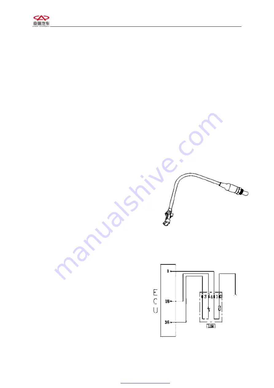
3.4 OXYGEN SENSOR
1)Exterior drawing and pin
There are 4 pins on this oxygen sensor
No. 1 connect to heating power anode (white)
No. 2 connects to heating power cathode (white)
No. 3 connects to signal cathode (gray)
No. 4 connects to signal anode (black)
2)Installation position: Assemble it on the top
of exhaust pipe.
3)Purpose:
The oxygen sensor checks the
oxygen percent in exhaust gases and transfer the
signal to ECU, and ECU will control the fuel
closed loop according to this information. This
will make engine working at its optimum
conditions. And transfer and purify CO, HC,
NO
x
compound in 3-way catalytic converter of
the tail gas maximally.
4)Working principle
Sensing element of oxygen sensor is a kind of
ceramic tube with holes, and outside of tube
walls are surrounded by engine exhaust gas and
inside is air. Ceramic sensor element is a kind of
solid state electrolyte with electrical heating
Chart 3-6 Exterior drawing of oxygen
sensor
Oxygen sensor
Main relay
Chart 3-7 circuit diagram of oxygen
sensor
PDF created with pdfFactory Pro trial version
Summary of Contents for A21 2005
Page 10: ...1 A21 ENGINE PDF created with pdfFactory Pro trial version www pdffactory com ...
Page 17: ...8 PDF created with pdfFactory Pro trial version www pdffactory com ...
Page 248: ......
Page 298: ......
Page 301: ... 5 5 8 7 5 0 LDJUDP H SODQDWLRQ LVWULEXWLRQ RI 9DULRXV DUWK 3RLQWV DQG 0DLQ 0RGXOHV ...
Page 303: ... 6 RQQHFWRU 6 5 5 8 7 5 0 211 725 127 8 RQQHFWRU 8 ...
Page 313: ... 12 5 5 8 7 5 0 GMXVWLQJ 6 XVH ER 6HDW DGMXVWLQJ V VWHP ...
Page 323: ... 5 5 8 7 5 0 12 FLJDUHWWH XVH ER V VWHP 1 7 21 ...