


The CA N data bus designed by the BOSCH c ompany is applied b y
Chery A5, sh own as fig ure 14-8. This enables the data communication of
eac h compute r, and forms the on-board network syst em. The in strument is
con nectted to the engine EMS
、
A BS
、
front ISU computer by CAN line and
sha re the data. The CA N end of instrumen t is 29
、
30
;
the CAN end of
eng ine ECU is 62
、
81
;
and the CAN end of front ISU is A25
、
A26.
①
BUS line test
The inspect of connect ca pability
、
open circuit or short circuit
、
com puter power or gro und.
②
Close the ign ition swi tch, cont rol the unit plug, and do not
connect the wiring harness plug at the tim e. Test the resistance between
the 62nd and 81st pin of A5 en gine control unit, this is the resistance
val ue of the d ata trasmission end port, the prescripti ve value is 123
Ω
, if it
is not so, please replace the engine control unit.
③
DTC logical d ecision.
④
Signal wavefor m test.
M
aintain way of the CAN data transmissio n system
A25
A26
C AN-H
CAN-L
29
30
81
62
ECU
Front ISU
Anti-Theft Horn
Horn Switch
Front ISU Fus e
F ront turn Lamp
Trunk Switch
Diagnosis Plug
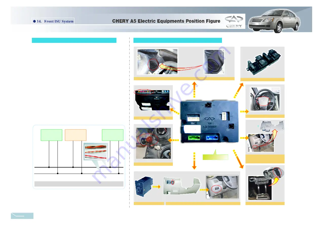
Installatio n position of front
e ngine compartmen t cover
a nd trunk switch
Installation positi on of night l amp and headlamp adjusting switch
Front Engine
Compartment
Cover Switch
8
.
Other position circuit diagram
7
.
CAN-BUS main line
Front ISU
Co mbination
In strument
Figure14-8 CAN-BUS main li ne
Door Contact Switch
3 2
Summary of Contents for A21 2005
Page 10: ...1 A21 ENGINE PDF created with pdfFactory Pro trial version www pdffactory com ...
Page 17: ...8 PDF created with pdfFactory Pro trial version www pdffactory com ...
Page 248: ......
Page 298: ......
Page 301: ... 5 5 8 7 5 0 LDJUDP H SODQDWLRQ LVWULEXWLRQ RI 9DULRXV DUWK 3RLQWV DQG 0DLQ 0RGXOHV ...
Page 303: ... 6 RQQHFWRU 6 5 5 8 7 5 0 211 725 127 8 RQQHFWRU 8 ...
Page 313: ... 12 5 5 8 7 5 0 GMXVWLQJ 6 XVH ER 6HDW DGMXVWLQJ V VWHP ...
Page 323: ... 5 5 8 7 5 0 12 FLJDUHWWH XVH ER V VWHP 1 7 21 ...