


33/40
Notes
11
Adjusting the barrier
The power supply and at least one switch OPEN-CLOSE must be connected. The barrier pole has
to be installed and balanced.
Attention: the traffic lane and the area surrounding the moving barrier pole must be
blocked from traffic in the mean time.
11.1
Adjustment of limit switches
The adjustment of limit switches is only possible if barrier pole is balanced.
The barrier can execute movements up to 90°.
Attention DANGER: Each time adjustments to limit switches are carried out the main switch
must be turned off. All operational components have to be secured to ensure that they
cannot be operated inadvertently.
Technically the Limit switch is a photocell which is located in a small case under the hood.
The limit is activated by a finger that interrupts the sensor beam. A LED indicates if a limit is
reached. Factory-provided the barrier is preset and only minor corrections should be needed,
if at all.
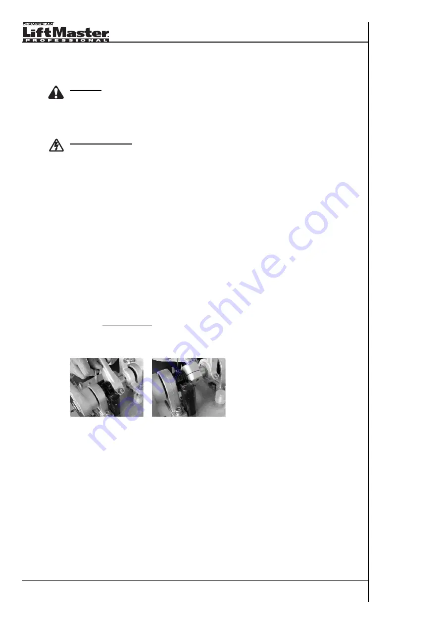
11.2 Correcting the limit switch adjustments
• turn off main switch
• remove barrier hood
• release barrier and lift into final position manually. The corresponding limit switch (LED on limit
switch) lights up, if the final position is reached electrically
o Correcting adjustments:
o Losen finger from shaft until it can be moved with little force.
o Move barrier to desired limit.
o The LED must light up in final position, but also as soon as final position is abandoned
Correct function: Barrier is switched off via Photocell and limit stop buffers are hardly or
only very slightly pushed in
• Turn on main switch and check result
11.3
Adjusting length of connecting arm between motor and barrier axle
The length of the pole has been adjusted ex works and must not be changed!
In case of adjustment being too short or too long the barrier does not reach the final position or
travels beyond final position. Then the slow travel at the end of the up or down movement does
not occur. The pole slightly touches on the limit buffers if correctly adjusted!


