Typical Applications
27
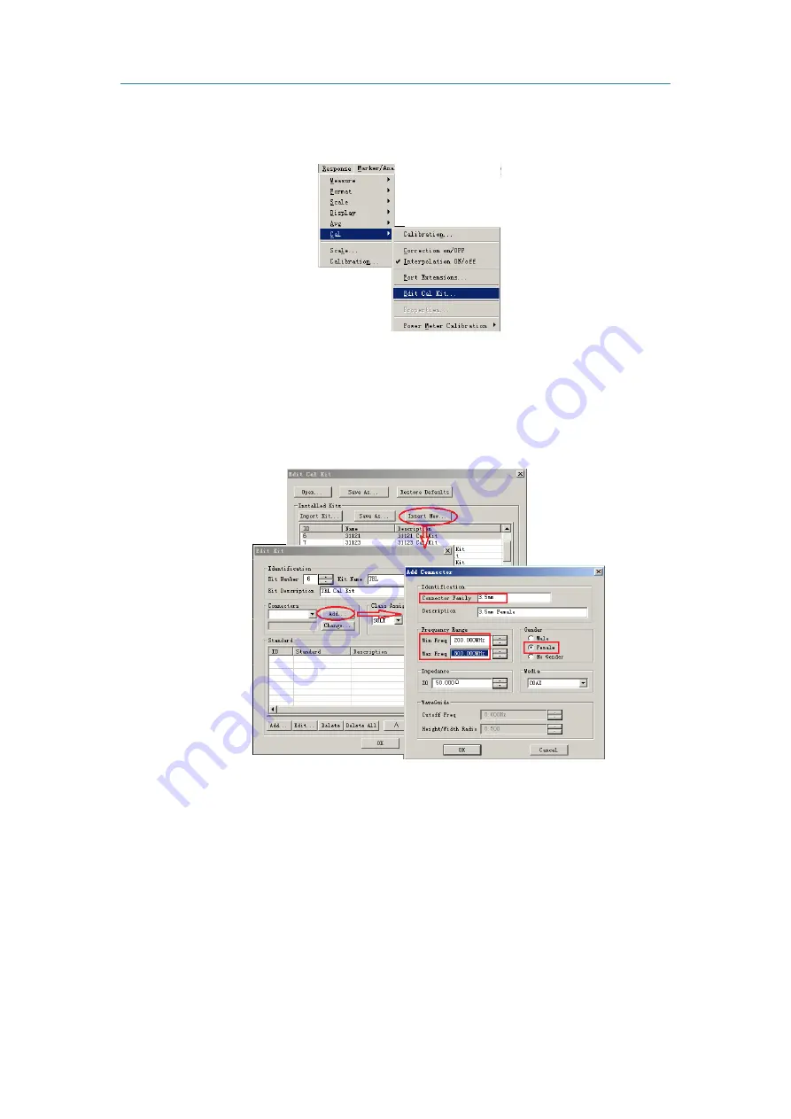
Click
[Response]
on the program main menu, as shown in below figure, click
[Edit Cal Kit...]
on
the
[Cal]
sub-menu, then
Edit Cal Kit
dialog box pops up.
Figure 3-26 Edit Cal Kit Menu
Click
[Insert New…]
on the
Edit Cal Kit
dialog box at the bottom of the following picture, a
dialog box pops up as shown by the arrow. Click
[Add]
,
Add Connector
dialog box pops up as shown by
the arrow. Then you can perform setting and add the new connector.
Figure 3-27 Add Connector
Set the parameters in the
Add Connector
dialog box: as shown by the red block in the above
picture, set the
Connector Family
as 3.5mm,
Min Freq
as 200MHz,
Max Freq
as 800MHz,
Gender
as
Female
, which the other items are in default. Then after clicking
[OK]
to close dialog box, it cannot edit
the characters of the connector.
After defining the connector, it needs to add the calibration standards, including OPEN, THRU and
transmission LINE in this example. As shown by the arrow in the following picture, click
Edit Kit
dialog
box and then click
[Add]
, the
Add Standard
dialog box will pop up.
Summary of Contents for 3656 Series
Page 1: ...1 3656 Series Vector Network Analyzer Quick Start Guide ...
Page 2: ......
Page 5: ......
Page 6: ......
Page 8: ......


