


63
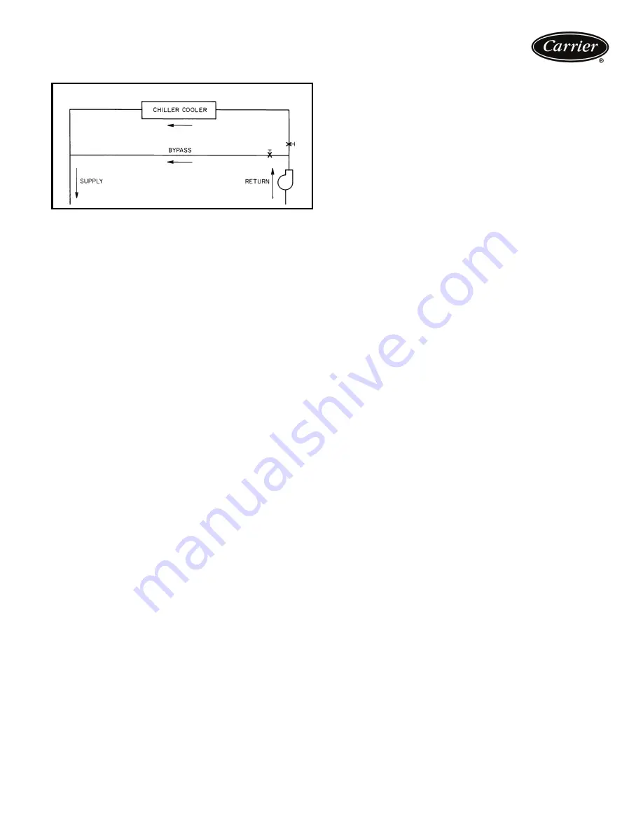
NOTE: Bypass flow is shown below.
Variable cooler flow rates
Variable flow rates may be applied to a standard chiller.
The unit will, however, attempt to maintain a constant
leaving chilled water temperature. In such cases, minimum
flow must be in excess of minimum flow given in the Mini-
mum and Maximum Cooler Fluid Flow Rates table on page
65, and minimum fluid volume in circulation must be in
excess of those values shown for normal air-conditioning
applications in the Minimum Fluid Volume in Circulation
table. Flow rate must change in steps of less than 10% per
minute. Apply 6 gal. or more per ton (6.5 L per kW) water
loop volume minimum if flow rate changes more rapidly.
The 30RAP chiller is available without a hydronic pump-
ing package, a constant-speed pumping package, or with a
variable-speed drive pumping package on sizes 070-090.
Traditional pumping systems incorporate constant speed
drives and waste energy by relying upon throttling valves as
the only means to control flow. A more energy-efficient
approach to this issue is use a variable-speed drive. The
30RAP070-090 units are now available with an optional
variable-speed hydronic package with sensorless technol-
ogy to meet this market requirement.
The major cost of a pump over its lifetime will be energy
consumption and maintenance, and both of these factors
will be reduced using variable-speed pumping. Energy is
saved by the combination of lowering the pump speed in
conjunction with the resulting lowering of pumping system
resistance when conditions permit. Maintenance benefits
from the sensorless pumping system include the lack of the
need to maintain remote sensors as well as the beneficial
effects of lower speed/pressure on the pump and pump
bearings.
Another advantage associated with variable-speed
pumping is reduced system noise in part-load operation
when the pump is running at lower speeds. The variable-
speed pump package offered on the 30RAP is offered
both in single and dual-pump designs. In the dual pump
case, in which one pump is the back-up of the other, each
pump connection is fitted with an isolation valve which
allows one pump to be isolated for service with the other
pump still operating.
As already mentioned, the 30RAP variable-speed
hydronic package employs sensorless technology. The
term "sensorless" means that no remote sensors are
required for pump operation. The sensorless pump
control monitors system requirements for pump speed and
power. The hydronic unit is provided with a pre-defined
control curve to automatically adjust speed at all operating
conditions. Pump performance and characteristic curves
for multiple speeds are programmed into the speed-con-
troller memory. The pre-programmed information includes
power, pressure and flow throughout the entire range of
the pump. During chiller operation, the power and speed
of the pump are monitored. This enables the controller to
establish the hydraulic performance, and to position the
pump's head-flow characteristic. Although this curve is pre-
defined, it is also fully field adjustable. The pump has a
graphical user interface, and the graphic keypad can also
be used to allow manual pump speed control.
This variable-speed pumping system easily connects to
BMS (Building Management System) systems (BACnet is
standard, and LON can be obtained via special order). The
pumps may be controlled directly by the BMS system. The
sensorless feature can also be switched off to allow the use
of either a 0 to 10 VDC signal or a 0 to 20 mA signal.
For multiple chiller applications employing the variable-
speed pumping package, such as chillers operated in a par-
allel arrangement, the drives must be connected by control
wiring and set up to run the same speed. This is to prevent
surging or hunting of the speed setpoint. One drive will act
as the master while the other slave drive will run at the
same speed. The master drive may be controlled by a 0 to
10 VDC signal, a 0 to 20 mA signal, or a BMS. The drive
must be configured to not use the sensorless function in
this arrangement.
A typical example of a chiller operating with a variable-
speed pumping system would be the case when the user
requires the chiller to operate with a constant fluid temper-
ature difference as the load is reduced. This can be accom-
plished with the 30RAP variable-speed pumping package
with the understanding that the minimum allowable flow
for the chiller must be respected. Once that limit is
reached, the flow cannot be further reduced. To accom-
plish this purpose, the minimum speed of the drive is pre-
set based upon the chiller size that is being employed.
As a specific example, let us say the schedule calls for a
90-ton, fresh-water chiller, and it is desired to have a con-
stant 10-degree temperature difference in part load opera-
tion (say 54 to 44 F). The schedule calls for 216 gpm at
full load based upon the desired capacity and the fluid tem-
perature difference. A constant temperature difference in
part load operation is essentially the same as providing
flow in direct proportion to chiller load. In the present
example, this means that 100% load will run at the sched-
uled 216 gpm, 90% load will be 194 gpm, etc. down to
the minimum allowable flow for this unit size, which, in the
case of a 30RAP090 unit, is 107 gpm. The chiller in this
example will therefore be able to run down to just under
50% load while approximately maintaining a constant 10
degree fluid temperature difference, and then the flow will
be held constant for all lower loads. Throughout the range
in which flow is reduced (down to minimum allowable
flow), the pump speed is proportionally reduced, resulting
in pump energy savings.
Fluid loop volume
The minimum volume of fluid required to be in circulation
is a function of the number of compressors in the chiller,
BYPASS FLOW
a30-533
Summary of Contents for Aquasnap 30RAP010
Page 14: ...14 a30 5349 Base unit dimensions 30RAP070 090...
Page 15: ...15 ACCESSORY STORAGE TANK FOR UNIT SIZES 010 015 a30 4879 Accessory dimensions...
Page 16: ...16 ACCESSORY STORAGE TANK FOR UNIT SIZES 018 030 a30 4880 Accessory dimensions cont...
Page 17: ...17 ACCESSORY STORAGE TANK FOR UNIT SIZES 035 060 a30 4881...
Page 60: ...60 600 760 a30 5264 Typical control wiring schematic...
Page 75: ......


