


92
isolation for certain service conditions when the isolation valve
package is specified.
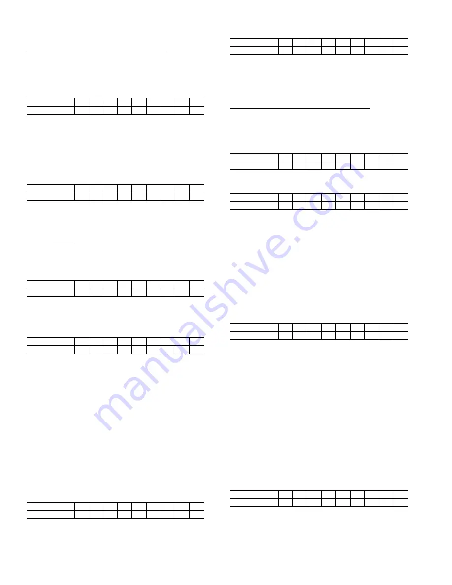
Transfer Refrigerant from Cooler to Condenser
a. Turn off chiller water pumps and pumpout con-
denser water supply (if applicable). It is assumed
that the starting point is as shown in the following
table and that pressures in both vessels are above
35 psig (241 kPa).
b. Keeping valves 7 and 8 closed, install charging
hose from liquid line charging valve 7 to valve 8
on the condenser float chamber. Evacuate or purge
hose of non-condensables. Note that this creates a
flow path between cooler and condenser that
bypasses the linear float, reducing the potential for
damage during refrigerant transfer.
c. Open valves 1A, 1B, 2, 5, and 8.
d. Turn on pumpout compressor, generating a refrig-
erant pressure differential of 10 to 20 psi
(69-138 kPa) to push liquid out of the chiller
cooler vessel.
e. Slowly open valve 7 to allow liquid transfer. Rapid
opening of valve 7 can result in float valve dam-
age.
f. When all liquid has been pushed into the chiller
condenser vessel, close valve 8.
g. Turn off the pumpout compressor.
h. Close pumpout valves 2 and 5 while opening valve
3 and 4 to prepare for removal of remaining refrig-
erant vapor in cooler vessel.
i. Turn on pumpout condenser water.
j. Turn on pumpout compressor. Turn on the chiller
water pump to establish water flow when the
cooler refrigerant pressure is 35 psig (241 kPa).
The water pumps have to be in operation when-
ever the refrigerant pressure is equal to or less
than 35 psig (241 kPa) to reduce the potential of
tube damage.
k. Run the pumpout compressor until the cooler pres-
sure reaches 35 psig (241 kPa), then turn off the
pumpout compressor. Warm chiller cooler water
will boil off any entrapped liquid refrigerant, and
chiller pressure will rise. Repeat this process until
the chiller pressure no longer rises.
l. Run pumpout unit in auto until the vacuum switch
is satisfied; this occurs at approximately 15 in. Hg
vacuum (48 kPa absolute or 7 psia). Close valve
1A.
m. Monitor that cooler pressure does not rise (if it
does, then repeat previous step).
n. With service valve 1A closed, shut down pumpout
compressor (if still running).
o. Close remaining valves.
p. Remove charging hose between 7 and 8 (evacuate
prior to removal).
q. Turn off pumpout condenser water.
r. Turn off chiller water pumps, and lockout chiller
compressor.
Transfer Refrigerant from Condenser to Cooler
a. Turn off chiller water pumps and pumpout con-
denser water supply (if applicable). It is assumed
that the starting point is as shown in the following
table and that pressures in both vessels are above
35 psig (241 kPa).
b. Set valves as shown below to allow the refrigerant
to equalize:
c. Turn on pumpout compressor, and develop a 10 to
20 psi (69 to 138 kPa) refrigerant differential pres-
sure between the vessels.
d. Partially open valve 11 while maintaining a refrig-
erant pressure differential to push liquid refrigerant
out of the chiller condenser to the cooler.
e. When all liquid is out of the chiller condenser,
close valve 11 and any other isolation valves on the
chiller.
f. Turn off the pumpout compressor.
g. Close pumpout valves 3 and 4 while opening valve
2 and 5 to prepare for removal of remaining refrig-
erant vapor in condenser vessel.
h. Turn on pumpout condenser water.
i. Turn on pumpout compressor.
j. Turn on the chiller water pumps, establishing water
flow when the condenser refrigerant pressure is 35
psig (241 kPa).
The water pumps have to be in
operation whenever the refrigerant pressure is
equal to or less than 35 psig (241 kPa) to reduce
the potential of tube damage.
k. Run the pumpout compressor until the condenser
refrigerant pressure reaches 35 psig (241 kPa) then
turn off the pumpout compressor. Warm condenser
water will boil off any entrapped liquid refrigerant,
and chiller pressure will rise. Repeat this process
until the chiller pressure no longer rises.
l. Run pumpout unit in auto until the vacuum switch
is satisfied; this occurs at approximately 15 in. Hg
vacuum (48 kPa absolute or 7 psia). Close
valve 1B.
m. Monitor that condenser pressure does not rise (if it
does, then repeat previous step).
n. With service valve 1B closed, shut down pumpout
compressor (if still running).
VALVE
1A
1B
2
3
4
5
7
8
11
CONDITION
C
C
C
C
C
C
C
C
C
VALVE
1A
1B
2
3
4
5
7
8
11
CONDITION
C
C
C
C
VALVE
1A
1B
2
3
4
5
7
8
11
CONDITION
C
C
C
C
VALVE
1A
1B
2
3
4
5
7
8
11
CONDITION
C
C
C
C
VALVE
1A
1B
2
3
4
5
7
8
11
CONDITION
C
C
C
C
C
VALVE
1A
1B
2
3
4
5
7
8
11
CONDITION
C
C
C
C
C
C
C
C
C
VALVE
1A
1B
2
3
4
5
7
8
11
CONDITION
C
C
C
C
C
C
C
C
C
VALVE
1A
1B
2
3
4
5
7
8
11
CONDITION
C
C
C
C
C
VALVE
1A
1B
2
3
4
5
7
8
11
CONDITION
C
C
C
C
C
VALVE
1A
1B
2
3
4
5
7
8
11
CONDITION
C
C
C
C
C
C
Summary of Contents for AquaEdge 19XR series
Page 69: ...69 Fig 33 19XR Leak Test Procedures a19 1625 ...
Page 154: ...154 Fig 64 Benshaw Inc Wye Delta Unit Mounted Starter Wiring Schematic Low Voltage a19 1873 ...
Page 161: ...161 Fig 69 Typical Low Voltage Variable Frequency Drive VFD Wiring Schematic 575 v ...
Page 162: ...162 Fig 69 Typical Low Voltage Variable Frequency Drive VFD Wiring Schematic 575 v cont ...
Page 186: ...186 APPENDIX B LEAD LAG WIRING 19XR Lead Lag Schematic Series Cooler Flow a19 1655 ...
Page 187: ...187 APPENDIX B LEAD LAG WIRING cont 19XR Lead Lag Schematic Parallel Cooler Flow a19 1717 ...