


106
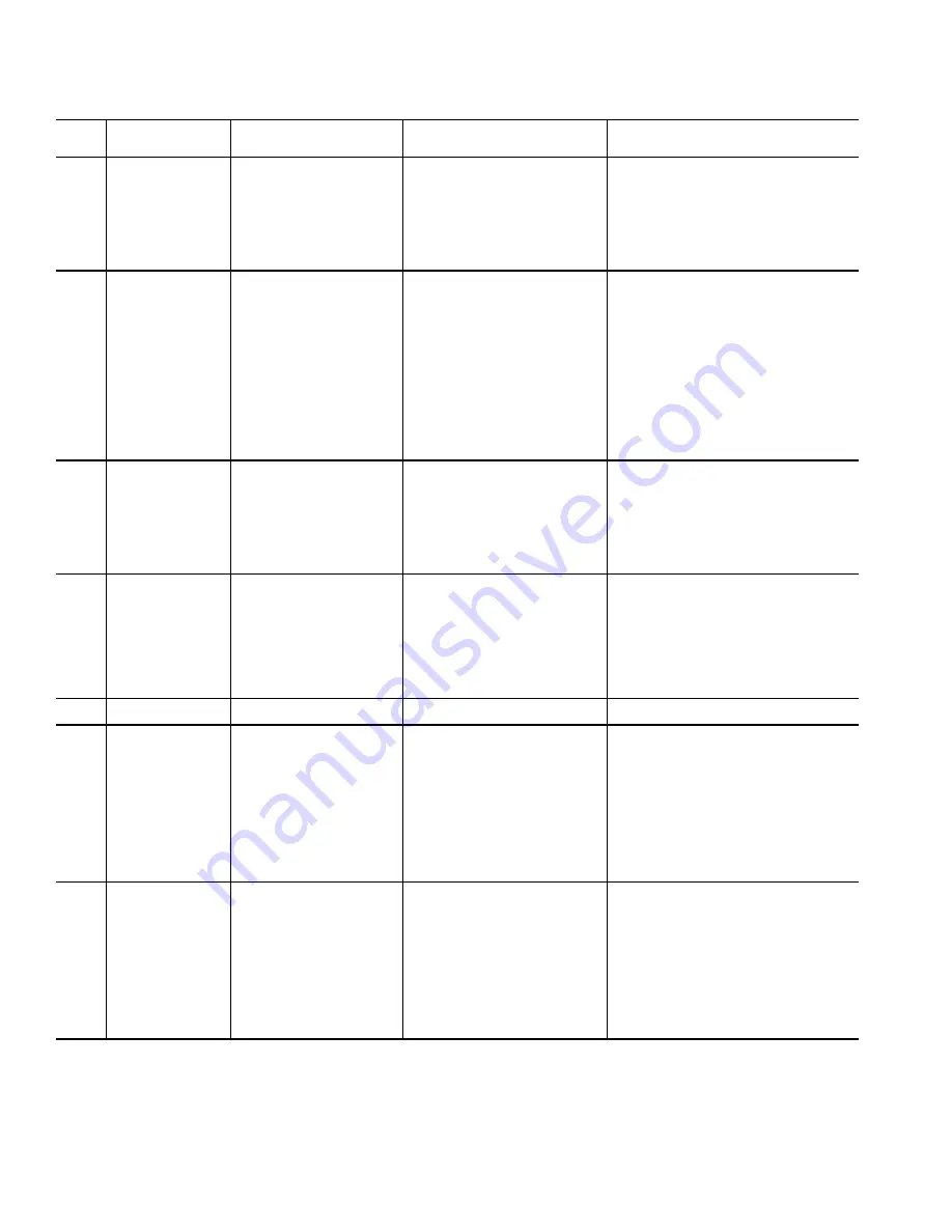
Table 16 — ICVC Primary and Secondary Messages and
Custom Alarm/Alert Messages with Troubleshooting Guides (cont)
I. CHILLER PROTECTIVE LIMIT FAULTS (cont)
*[LIMIT] is shown on the ICVC as the temperature, pressure, voltage, etc., set point predefined or selected by the operator as an override, alert, or alarm condition.
[VALUE] is the actual pressure, temperature, voltage, etc., at which the control tripped. "Exceeded Limit" in Alarm or Alert messages may mean the value is above or
below a threshold
.
ICVC
FAULT
STATE
PRIMARY MESSAGE
SECONDARY MESSAGE
PRIMARY CAUSE
ADDITIONAL
CAUSE/REMEDY
233
PROTECTIVE LIMIT
HIGH MOTOR TEMPERATURE
233->Comp Motor Winding Temp
[VALUE] exceeded limit of [LIMIT]*.
Check COMP MOTOR WINDING TEMP accuracy
and wiring to CCM J4-23 and J4-24.
Check motor cooling line and spray nozzle for
proper operation, or restrictions. Check motor
cooling filter/drier and isolation valves. Look for
refrigerant flow through motor cooling line sight
glass.
Check for excessive starts within a short time
span. Check temperature after switching to spare
COMP MOTOR WINDING TEMP sensor.
234
PROTECTIVE LIMIT
HIGH BEARING TEMPERA-
TURE
234->Comp Thrust Brg Temp [VALUE]
exceeded limit of [LIMIT]*.
Check oil heater for proper operation, confirm that
oil heater is de-energized when compressor is run-
ning. Check for low oil level, partially closed oil line
isolation valves, or clogged oil filter. Check oil
cooler refrigerant thermal expansion valves, con-
firm that expansion valve bulbs are secured to the
oil lines and insulated. Check COMP THRUST
BRNG TEMP sensor accuracy and wiring to CCM
J4-19 and J4-20. Check temperature after switch-
ing to spare COMP THRUST BRNG TEMP sen-
sor. This fault can result from excessive operation
at low load with low water flow to the evaporator or
condenser. Very high discharge and volute tem-
peratures may increase the oil sump temperature.
Elevated sump temperature may result from an
excessively high oil level reaching the bottom of
the bull gear causing it to churn the oil.
235
PROTECTIVE LIMIT
HIGH CONDENSER PRESSURE 235->Condenser Pressure [VALUE]
exceeded limit of [LIMIT]*.
Check CONDENSER PRESSURE. Check for high
Condenser Water temperatures, low water flow,
fouled tubes. Check for division plate/gasket
bypass or plugged condenser water strainers.
Check for noncondensables in condenser. Check
CONDENSER PRESSURE transducer wiring and
accuracy to CCM J2-4 through J2-6. Configure
COND PRESS OVERRIDE in SETUP1 screen.
This Alarm is not caused by the High Condenser
Pressure Switch.
236
PROTECTIVE LIMIT
COMPRESS SURGE/LOW
SPEED
236->Compressor Surge: Check con-
denser water temp and flow
Surge prevention alarm declared before ACTUAL
VFD SPEED reached 90%. Check for high CON-
DENSER PRESSURE, high Condenser Water
temperatures, low water flow, fouled tubes. Check
condenser water strainers. Check CONDENSER
APPROACH. Check for division plate/gasket
bypass. Check for noncondensables in condenser.
Check surge prevention parameters in OPTIONS
screen. Increase VFD INCREASE STEP in SET-
UP2. Check VFD MINIMUM SPEED in SETUP2
screen.
237
PROTECTIVE LIMIT
SPARE SAFETY DEVICE
237->Spare Safety Device
Spare safety input has tripped or factory installed
jumper is not present on ISM J2-1 and J2-2.
238
PROTECTIVE LIMIT
EXCESSIVE COMPR SURGE
238->Compressor Surge: Check con-
denser water temp and flow
Five SURGE PROTECTION COUNTS occurred
within SURGE TIME PERIOD. VFD Only: Surge
prevention alarm declared when ACTUAL VFD
SPEED is at least 90%. Check for high condenser
water temperatures, low water flow, fouled tubes.
Check CONDENSER APPROACH. Check con-
denser water strainers. Check for division plate/
gasket bypass. Check for noncondensables in
condenser. Check surge prevention parameters in
OPTIONS screen. Compare cooling tower control
settings and performance against design/selection
temperatures across the entire operating range of
the chiller. Check EVAPORATOR APPROACH
and chilled water flow.
239
PROTECTIVE LIMIT
TRANSDUCER VOLTAGE
FAULT
239->Transducer Voltage Ref [VALUE]
exceeded limit of [LIMIT]*.
Check that TRANSDUCER VOLTAGE REF is
between 4.5 V and 5.5 V in the CCM PRESSURE
TRANSDUCERS screen. Check that none of the
pressure transducers are shorted to ground. Con-
firm TRANSDUCER VOLTAGE REF by measur-
ing voltage across a CCM Pressure Transducer
(e.g. CCM J2-1 to J2-3). Check TRANSDUCER
VOLTAGE REF after temporarily disconnecting
chiller from CCN and disconnecting field wiring
from CCM terminal blocks J5 and J8. This fault is
normally declared the first time an ICVC is pow-
ered up if it was downloaded with software when it
was not connected to a CCM. Check for 24V
across CCM J1-1 and J1-2. Call Carrier Service.
Summary of Contents for AquaEdge 19XR series
Page 69: ...69 Fig 33 19XR Leak Test Procedures a19 1625 ...
Page 154: ...154 Fig 64 Benshaw Inc Wye Delta Unit Mounted Starter Wiring Schematic Low Voltage a19 1873 ...
Page 161: ...161 Fig 69 Typical Low Voltage Variable Frequency Drive VFD Wiring Schematic 575 v ...
Page 162: ...162 Fig 69 Typical Low Voltage Variable Frequency Drive VFD Wiring Schematic 575 v cont ...
Page 186: ...186 APPENDIX B LEAD LAG WIRING 19XR Lead Lag Schematic Series Cooler Flow a19 1655 ...
Page 187: ...187 APPENDIX B LEAD LAG WIRING cont 19XR Lead Lag Schematic Parallel Cooler Flow a19 1717 ...