


91
Transfer Refrigerant from Storage Tank Vessel to Chiller
1. Equalize refrigerant pressure.
a. Turn on chiller water pumps, establishing water
flow (assumes vacuum condition in chiller sys-
tem).
b. Close pumpout and storage tank valves 2, 4, 5, 7,
8, 10 (if present open isolation valve 11 and other
isolation valves between cooler and condenser).
Open storage tank valves 6; open chiller valves 1A
and 1B.
c. Gradually open valve 5 to slowly increase chiller
pressure to 35 psig (241 kPa) to reduce the poten-
tial of tube freeze up.
d. Open valve 5 fully after the chiller pressure
reaches 35 psig (241 kPa) or greater. Let chiller
pressure reach 40 psig (276 kPa), then chiller water
pumps can be turned off. Fully close valve 5.
e. Open valve 8 and 10 to let higher pressure in the
recovery tank push liquid refrigerant into the con-
denser float chamber and heat exchangers until the
refrigerant pressure equalizes between the recov-
ery tank and chiller.
2. Push liquid to chiller, them remove remaining vapor from
storage tank:
a. To prepare for liquid, push open valve 4.
b. Ensure pumpout condenser water is off, then turn
on the pumpout compressor in manual mode to
push liquid to chiller. Monitor the storage tank
level until tank is empty of liquid refrigerant.
c. Close charging valves 8 and 10.
d. Turn off the pumpout compressor.
e. To prepare for removal of remaining refrigerant
vapor in storage tank, close pumpout valves 3 and
4 and open valves 2 and 5.
f. Turn on pumpout condenser water.
g. Run pumpout unit in auto until the vacuum switch
is satisfied. This occurs approximately at 15 in Hg
vacuum (48 kPa absolute or 7 psia), removing the
residual refrigerant vapor from the recovery tank
and condensing to a liquid in the chiller.
h. Close valves 1A, 1B, 2, 5, 6.
i. Turn off pumpout condenser water.
Transfer Refrigerant from Chiller to Storage Tank Vessel
1. Equalize refrigerant pressure.
a. Dehydrate the refrigerant storage vessel, and con-
nected hoses/piping so there are no non-condens-
ables mixed with the refrigerant.
b. Locate valves as identified below:
c. Slowly open valve 5 until the refrigerant pressure
reaches 35 psig (241 kPa) in the storage tank, fol-
lowed by valves 7 and 10 to allow liquid refriger-
ant to drain by gravity.
2. Push remaining liquid, followed by refrigerant vapor re-
moval from chiller.
a. To prepare for liquid push, turn off the pumpout
condenser water. Place valves in the following
positions:
b. Run the pumpout compressor in manual until all
liquid is pushed out of the chiller (approximately
45 minutes). Close valves 2, 5, 7, and 10, then stop
compressor.
c. Turn on pumpout condenser water.
d. Open valves 3 and 4, and place valves in the fol-
lowing positions:
e. Run the pumpout compressor until the chiller pres-
sure reaches 35 psig (241 kPa), followed by turn-
ing off the pumpout compressor. Warm chiller
condenser water will boil off any entrapped liquid
refrigerant, and chiller pressure will rise.
f. When chiller pressure rises to 40 psig (276 kPa),
turn on the pumpout compressor until the pressure
reaches 35 psig (241 kPa) again; then turn off the
pumpout compressor. Repeat this process until the
chiller pressure no longer rises.
g. Start the chiller water pumps (condenser and
cooler), establishing water flow. At this point, turn
on the pumpout compressor in auto until the vac-
uum switch is satisfied. This occurs at approxi-
mately 15 in Hg vacuum (48 kPa absolute or
7 psia).
h. Close valves.
i. Turn off the pumpout condenser water.
CHILLERS WITH ISOLATION VALVES — The valves re-
ferred to in the following instructions are shown in Fig. 43 and
44. The cooler/condenser vessels can be used for refrigerant
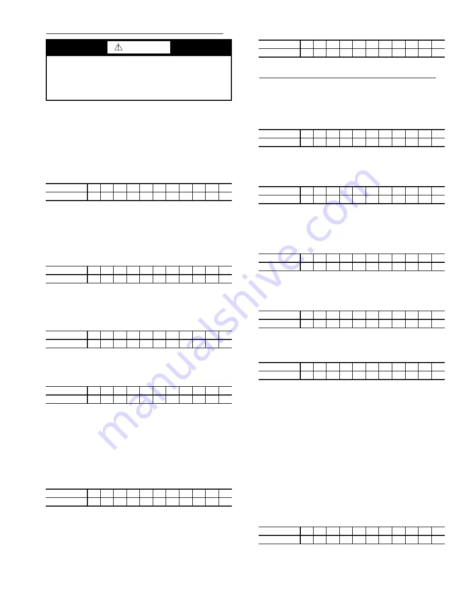
WARNING
During transfer of refrigerant into and out of the
19XR,XRV storage tank, carefully monitor the storage
tank level gage. Do not fill the tank more than 90% of
capacity to allow for refrigerant expansion. Overfilling
may result in damage to the tank and personal injury.
VALVE
1A 1B
2
3
4
5
6
7
8
10
11
CONDITION
C
C
C
C
C
C
VALVE
1A 1B
2
3
4
5
6
7
8
10
11
CONDITION
C
C
C
C
C
C
VALVE
1A 1B
2
3
4
5
6
7
8
10
11
CONDITION
C
C
C
C
VALVE
1A 1B
2
3
4
5
6
7
8
10
11
CONDITION
C
C
C
VALVE
1A 1B
2
3
4
5
6
7
8
10
11
CONDITION
C
C
C
C
C
VALVE
1A 1B
2
3
4
5
6
7
8
10
11
CONDITION
C
C
C
C
C
C
C
C
C
C
VALVE
1A 1B
2
3
4
5
6
7
8
10
11
CONDITION
C
C
C
C
C
C
VALVE
1A 1B
2
3
4
5
6
7
8
10
11
CONDITION
C
C
C
VALVE
1A 1B
2
3
4
5
6
7
8
10
11
CONDITION
C
C
C
VALVE
1A 1B
2
3
4
5
6
7
8
10
11
CONDITION
C
C
C
C
C
C
C
VALVE
1A 1B
2
3
4
5
6
7
8
10
11
CONDITION
C
C
C
C
C
VALVE
1A 1B
2
3
4
5
6
7
8
10
11
CONDITION
C
C
C
C
C
C
C
C
C
C
Summary of Contents for AquaEdge 19XR series
Page 69: ...69 Fig 33 19XR Leak Test Procedures a19 1625 ...
Page 154: ...154 Fig 64 Benshaw Inc Wye Delta Unit Mounted Starter Wiring Schematic Low Voltage a19 1873 ...
Page 161: ...161 Fig 69 Typical Low Voltage Variable Frequency Drive VFD Wiring Schematic 575 v ...
Page 162: ...162 Fig 69 Typical Low Voltage Variable Frequency Drive VFD Wiring Schematic 575 v cont ...
Page 186: ...186 APPENDIX B LEAD LAG WIRING 19XR Lead Lag Schematic Series Cooler Flow a19 1655 ...
Page 187: ...187 APPENDIX B LEAD LAG WIRING cont 19XR Lead Lag Schematic Parallel Cooler Flow a19 1717 ...