


73
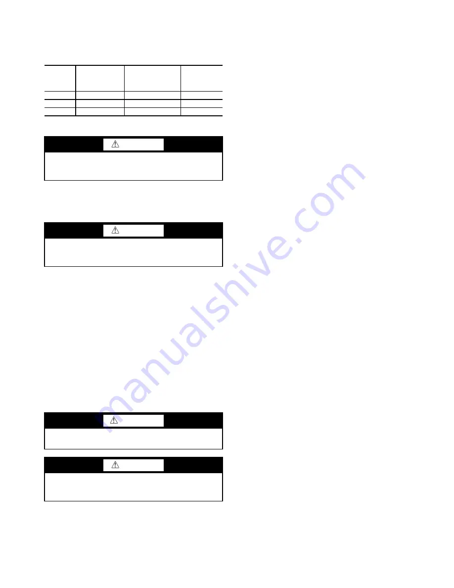
When connecting the CCN communication bus to a system
element, a color code system for the entire network is recom-
mended to simplify installation and checkout. The following
color code is recommended:
Check Starter
Use the instruction and service manual supplied by the start-
er manufacturer to verify the starter has been installed correct-
ly, to set up and calibrate the starter, and for complete trouble-
shooting information.
MECHANICAL STARTER
1. Check all field wiring connections for tightness, clear-
ance from moving parts, and correct connection.
2. Check the contactor(s) to ensure they move freely. Check
the mechanical interlock between contactors to ensure
that 1S and 2M contactors cannot be closed at the same
time. Check all other electro-mechanical devices, such as
relays, for free movement. If the devices do not move
freely, contact the starter manufacturer for replacement
components.
3. Reapply starter control power (
not main chiller power
) to
check the electrical functions.
Ensure the starter (with relay 1CR closed) goes through a
complete and proper start cycle.
BENSHAW, INC. RediStart MX3™ SOLID-STATE
STARTER
1. Ensure all wiring connections are properly terminated to
the starter.
2. Verify the ground wire to the starter is installed properly
and is sufficient size.
3. Verify the motors are properly grounded to the starter.
4. Verify the proper ac input voltage is brought into the start-
er according to the certified drawings.
5. Apply power to the starter
VFD STARTER
1. Turn off unit, tag and lock disconnects and wait 5 minutes.
2. Verify that the DC voltage is zero.
3. Ensure there is adequate clearance around the drive.
4. Verify that the wiring to the terminal strip and power ter-
minals is correct.
5. Verify that wire size is within the terminal specification
and the wires are secure.
6. Inspect the field supplied branch circuit protection is
properly rated and installed.
7. Verify that the system is properly grounded.
8. Inspect all liquid cooling connections for leaks.
Oil Charge —
The oil charge for the 19XR compressor de-
pends on the compressor Frame size:
• Frame 2 compressor — 8 gal (30 L)
• Frame 3 compressor — 8 gal (30 L)
• Frame 4 compressor — 10 gal (37.8 L)
• Frame 4 compressor with split ring diffuser option —
12 gal (45.0 L)
• Frame 5 compressor — 18 gal (67.8 L)
• Frame E compressor — 18 gal (67.8 L)
The chiller is shipped with oil in the compressor. When the
sump is full, the oil level should be no higher than the middle
of the upper sight glass, and minimum level is the bottom of
the lower sight glass (Fig. 2 and 3). If oil is added, it must meet
Carrier’s specification for centrifugal compressor use as de-
scribed in the Oil Specification section. Charge the oil through
the oil charging valve located near the bottom of the transmis-
sion housing (Fig. 2 and 3). The oil must be pumped from the
oil container through the charging valve due to higher refriger-
ant pressure. The pumping device must be able to lift from 0 to
200 psig (0 to 1380 kPa) or above unit pressure. Oil should
only be charged or removed when the chiller is shut down.
Power Up the Controls and Check the Oil
Heater —
Ensure that an oil level is visible in the compres-
sor and the chiller is not in an vacuum before energizing the
controls. A circuit breaker in the starter energizes the oil heater
and the control circuit. When first powered, the ICVC should
display the default screen within a short period of time.
The oil heater is energized by powering the control circuit.
This should be done several hours before start-up to minimize
oil-refrigerant migration. The oil heater is controlled by the
PIC II and is powered through a contactor in the power panel.
A separate circuit breaker powers the heater and the control cir-
cuit. This arrangement allows the heater to energize when the
main motor circuit breaker is off for service work or extended
shutdowns. The oil heater relay status (
OIL HEATER RELAY
)
can be viewed on the COMPRESS table on the ICVC. Oil
sump temperature can be viewed on the ICVC default screen.
SOFTWARE VERSION — The software part number is la-
beled on the backside of the ICVC module. The software ver-
sion also appears on the ICVC CONFIGURATION screen as
the last two digits of the software part number.
SIGNAL
TYPE
CCN BUS
CONDUCTOR
INSULATION
COLOR
CCN TERMINAL
CONNECTION
ICVC PLUG
J1 PIN NO.
+
Red
RED (+)
1
GROUND
White
WHITE (G)
2
–
Black
BLACK (–)
3
CAUTION
BE AWARE that certain automatic start arrangements
can
engage the starter
. Open the disconnect
ahead
of the starter
in addition to shutting off the chiller or pump.
CAUTION
The main disconnect on the starter front panel may not
deenergize all internal circuits. Open all internal and
remote disconnects before servicing the starter.
WARNING
This equipment is at line voltage when AC power is con-
nected. Pressing the STOP button does not remove voltage.
CAUTION
An isolation switch or circuit breaker must be open ahead
of any VFD or solid-state starter when the chiller is in a
vacuum. If not, damage to the machine may result.
Summary of Contents for AquaEdge 19XR series
Page 69: ...69 Fig 33 19XR Leak Test Procedures a19 1625 ...
Page 154: ...154 Fig 64 Benshaw Inc Wye Delta Unit Mounted Starter Wiring Schematic Low Voltage a19 1873 ...
Page 161: ...161 Fig 69 Typical Low Voltage Variable Frequency Drive VFD Wiring Schematic 575 v ...
Page 162: ...162 Fig 69 Typical Low Voltage Variable Frequency Drive VFD Wiring Schematic 575 v cont ...
Page 186: ...186 APPENDIX B LEAD LAG WIRING 19XR Lead Lag Schematic Series Cooler Flow a19 1655 ...
Page 187: ...187 APPENDIX B LEAD LAG WIRING cont 19XR Lead Lag Schematic Parallel Cooler Flow a19 1717 ...