


17
Other than the unit-mounted starter or drive options dis-
cussed above, 19XR chillers may be provided with other alter-
natives such as free-standing low voltage or medium voltage
starters, or free-standing variable frequency drives. These are
usually specified in the original sales requisition. Features and
functionality included with these alternative starters are defined
in Carrier specifications such that operation with PIC II con-
trols remains consistent.
CONTROLS
Definitions
ANALOG SIGNAL —
An analog signal
varies in proportion
to the monitored source. It quantifies values between operating
limits. (Example: A temperature sensor is an analog device be-
cause its resistance changes in proportion to the temperature,
generating many values.)
DISCRETE SIGNAL —
A discrete signal
is a 2-position rep-
resentation of the value of a monitored source. (Example: A
switch produces a discrete signal indicating whether a value is
above or below a set point or boundary by generating an on/off,
high/low, or open/closed signal.)
General —
The 19XR hermetic centrifugal liquid chiller
contains a microprocessor-based control center that monitors
and controls all operations of the chiller (see Fig. 12). The mi-
croprocessor control system matches the cooling capacity of
the chiller to the cooling load while providing state-of-the-art
chiller protection. The system controls cooling load within the
set point plus the deadband by sensing the leaving chilled water
or brine temperature and regulating the inlet guide vane via a
mechanically linked actuator motor. The guide vane is a
variable flow pre-whirl assembly that controls the refrigeration
effect in the cooler by regulating the amount of refrigerant va-
por flow into the compressor. An increase in guide vane
opening increases capacity. A decrease in guide vane opening
decreases capacity. The microprocessor-based control center
protects the chiller by monitoring the digital and analog inputs
and executing capacity overrides or safety shutdowns, if re-
quired.
PIC II System Components —
The chiller control
system is called the PIC II (Product Integrated Control II). See
Table 1. The PIC II controls the operation of the chiller by
monitoring all operating conditions. The PIC II can diagnose a
problem and let the operator know what the problem is and
what to check. It promptly positions the guide vanes to main-
tain leaving chilled water temperature. It can interface with
auxiliary equipment such as pumps and cooling tower fans to
turn them on when required. It continually checks all safeties to
prevent any unsafe operating condition. It also regulates the oil
heater while the compressor is off and regulates the hot gas by-
pass valve, if installed. The PIC II controls provide critical pro-
tection for the compressor motor and controls the motor starter.
The PIC II can interface with the Carrier Comfort Net-
work
®
(CCN) if desired. It can communicate with other PIC I,
PIC II or PIC III equipped chillers and other CCN devices.
The PIC II consists of 3 modules housed inside 3 major
components. The component names and corresponding control
voltages are listed below (also see Table 1):
• control panel
— all extra low-voltage wiring (24 v or less)
• power panel
— 115 v control voltage transformer primaries (may be
rewired to accomodate 230 vac)
— 115 vac power for oil heater and actuators (oil heaters
may be rewired to accomodate 230 vac)
— up to 575 v for oil pump power
• starter cabinet
— chiller power wiring (per job requirement)
57.17
54.54
60.00
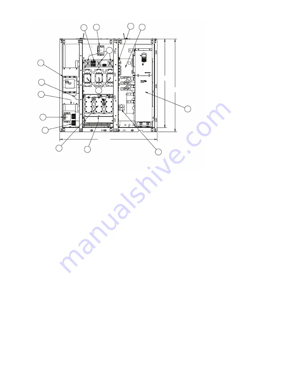
INPUT INDUCTOR
BEHIND CAP
ASSEMBLY
12
15
14
13
6
8
7
9
1
2
3
4
5
11
10
3KVA X-FORMER
BEHIND
THE 15AMP CB
Fig. 11 — PIC II Unit-Mounted 575-v Variable Frequency Drive (VFD) Internal View
LEGEND
1
— Main Power Circuit Breaker (CB)
2
— Electric Surge Protector
3
— Control Transformer
4
— Contr Power CB
5
— Control Power Fuse
6
— Oil Pump CB
7
— Pre-Charge Resistors
8
— Pre-Charge Fuses
9
— Pre-Charge Contactors
10
— Input line Reactor
11
— Capacitor Filter Bank
12
— Input Current Transformers
13
— Interface Relays
14
— ISM
15
— VFD Power Module
Summary of Contents for AquaEdge 19XR series
Page 69: ...69 Fig 33 19XR Leak Test Procedures a19 1625 ...
Page 154: ...154 Fig 64 Benshaw Inc Wye Delta Unit Mounted Starter Wiring Schematic Low Voltage a19 1873 ...
Page 161: ...161 Fig 69 Typical Low Voltage Variable Frequency Drive VFD Wiring Schematic 575 v ...
Page 162: ...162 Fig 69 Typical Low Voltage Variable Frequency Drive VFD Wiring Schematic 575 v cont ...
Page 186: ...186 APPENDIX B LEAD LAG WIRING 19XR Lead Lag Schematic Series Cooler Flow a19 1655 ...
Page 187: ...187 APPENDIX B LEAD LAG WIRING cont 19XR Lead Lag Schematic Parallel Cooler Flow a19 1717 ...