Chapter 3
3-13
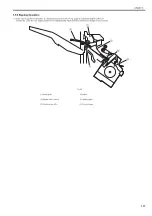
3.4.5 Buffer Operation
0020-4722
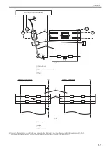
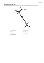
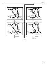
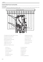
The finisher controller PCB keeps a sheet of paper in the paper path and forwards it together with the subsequent sheet of paper using the buffer motor (M4) and
the buffer path switching solenoid (SL1) with the help of the buffer path 1 sensor PCB and the buffer path 2 sensor PCB (UN13, UN14).
F-3-18
M4: Buffer motor
UN13: Buffer path 1 sensor PCB
SL1: Buffer path switching solenoid
UN14: Buffer path 2 sensor PCB
M4
SL1
UN14
UN13
Finisher controller PCB
Buffer path
Summary of Contents for Saddle Finisher-AF2
Page 1: ...SERVICE MANUAL Saddle Finisher AF2 MARCH 6 2009...
Page 2: ......
Page 6: ......
Page 12: ...Contents...
Page 13: ...Chapter 1 Specifications...
Page 14: ......
Page 16: ......
Page 22: ......
Page 23: ...Chapter 2 Installation...
Page 24: ......
Page 26: ......
Page 55: ...Chapter 3 Functions...
Page 56: ......
Page 58: ......
Page 104: ...Chapter 3 3 46...
Page 105: ...Chapter 4 Parts Replacement Procedure...
Page 106: ......
Page 110: ......
Page 157: ...Chapter 4 4 47 F 4 213 3 2 1...
Page 158: ......
Page 159: ...Chapter 5 Maintenance...
Page 160: ......
Page 209: ...Chapter 5 5 47 F 5 221 SW382 SW381 SW383 ENTER SW384 SW385 DSP381 1...
Page 218: ......
Page 219: ...Appendix...
Page 220: ......
Page 221: ...General Timing Chart General Circuit Diagram Finisher Sorter DeliveryTray Saddle Finisher AF2...
Page 222: ......
Page 224: ......
Page 225: ...Contents 1 General Circuit Diagram 1 Signal Names 1 General Circuit Diagram 9...
Page 226: ......
Page 243: ......
Page 244: ......


